


Rev. P. Dokument N Signature Data
ТЭ3.623.912-03РЭ ТЭ3.623.912-03РЭ
Rev. P. Dokument N Signature Data
Size А3 /А4
Signature and Data
Invent N of doubl
Subst. of invent N
Signature and Data
Invent N of orig.
2 OPERATION
2.1 Operating Conditions and Safety Rules
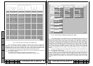
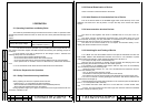
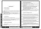
The maximum permissible ratings of the device are shown in Table 4. Operation under
stresses beyond these maximum limits is unsafe and can cause permanent damage to the
device.
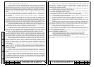
Table 4
Technical Parameter Maximum Limit Note
Primary side supply voltage
≈231 V, continuous
≈249 V, transient, up to 3 s
2.1.1 The device should be operated only by qualified personnel acquainted with this
OM, electric connection diagram ТЭ3.623.912-03Э4 and knowing the operating principle of
the device.
2.1.2 The device is fed with a dangerous for life voltage of 220 V. Therefore the
following safety rules must be observed:
- do not use the device without reliable grounding;
- do not use the device with its side or rear covers removed;
- do not use self-made fuses or those with ratings different from the recommended;
- never replace fuses or modules, connect or disconnect any cables when the device
is on.
2.1.3. No mechanical works should be done while the device is switched on.
2.2 Device Preparation for Operation
2.2.1 Safety Precautions during Installation
When preparing the device for operation make sure that:
- bonding point "⊥" is connected to the hull of the object;
- all the modules are installed and fastened in their dedicated positions;
- all the fuses are installed and fixed in the holders.
During operation, bright rays of light from external sources of light should not fall onto
the screen of the BC-2 TVM.
2.2.2 External Examination of Device
Check connection of external cables to the device.
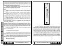
2.2.3 Initial Position of Controls before Use of Device
Prior to the device switch-on the POWER toggle switch under the drop cover of the
assembly unit should be in the off position. To open the drop cover unscrew the captive
screws.
2.2.4 Interconnection wit other Devices
The device is used together with device "Гном-2МЭ" that is not a part of the TV-
complex.
The device receives chronometrical information from "Гном-2МЭ" device via a line
with transformer decoupling. No reply information is transmitted to the "Гном-2МЭ" device.
The device state does not influence on operation of "Гном-2МЭ".
The device is the central module of the TV-complex and interacts directly or non-
directly with all the modules of the TV-complex.
2.2.5 Switching-On and Testing of Device
2.2.5.1 Make sure that the POWER switch on the ЩР-03 switchboard and also the
МТК-110МЭ, PANELS and PERISCOPE switches are turned on. The indicators of phase
voltage presence should light, phase voltages should be from 180 to 231 V.
2.2.5.2 Open the drop cover of the assembly unit.
Open the door of the device by rotating counter-clockwise the clamping nuts of the
locks and putting the handles of the locks into the "UNLK" position.
2.2.5.3 Switch on the POWER toggle switch under the drop cover of the assembly
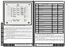
unit. The following indicators should light up:
- presence of phase voltages, "P1", "P2", "P3"; this indicators are mounted on the front
panel of the assembly unit;
- "27V" on the front panel of the ВС-2 TVM;
- 16 indicators on the fuse panel of the fifth floor of the device;
- two indicators on еach of the front panels of the three ЭМ-1213 power supply units.
2.2.5.4 Turn on the
ВС-2 TVM by pressing the ON button. After this the indicator near
the ON button should light up.
Adjust brightness and contrast with the buttons on the TVM front panel as described in
item 1.2.1.3. of the present OM if necessary.
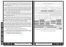
2.2.5.5 Press the button TEST ЭМ-1212-1 on the ЭМ-1212-1 control module. After
that:
- by turns, from top to bottom and from left to right, the red LEDs under the TROUBLE
inscription will light up and then go out;
P. P.
30
29