


Rev. P. Dokument N Signature Data
ТЭ3.623.912-03РЭ
ТЭ3.623.912-03РЭ
Rev. P. Dokument N Signature Data
Size А3 /А4
Signature and Data
Invent N of doubl
Subst. of invent N
Signature and Data
Invent N of orig.
- receiver operation threshold is from 5 to 8 mA.
Data in the RCLI channels is transmitted as byte arrays. Data arrays are transferred
with a frequency from 10 to 25 Hz. The pause between arrays is no less than 1 ms. Pause
between neighboring bytes within an array is no more than 100 µS. Every array ends with a
check sum. Data exchange in RCLI channels is started by the ЭМ-1209-1 controller by
transmission of the corresponding command instruction arrays. On reception of the command
instruction array all the units and modules of the TV-complex start transmission of reply
arrays.
Data exchange between the ЭМ-1209-1 controller and the ТМ-1304 No.1 -
ТМ-1304 No.5. combined modules is performed via channels " RCLI 1" – " RCLI 5". During
this exchange the datastream passes through assembly modules, ТМ-1308 No.1-
ТМ-1308 No.3.
Every command array consists of nine bytes and contains the following data:
command to switch on the power supplies of four TVDs, video signal correction factors for
four TVDs, type of synchronizing pulses and delay of those for synchronization of four TVDs,
instructions for control of TVD modes. The reply arrays contain data on functioning of the
modules that are parts of the ТМ-1304 combined modules, supply voltage presence on four
TVDs, presence of video signals from four TVDs, diagnostic information from four TVDs.
Data exchange between the ЭМ-1209-1 controller and the ТМ-1213 terminal module
is performed via channel " RCLI 7". During this exchange the datastream passes through
connector X38 of the device and the ТМ-1308 No.4 assembly module.
The command array contains commands to light up the LEDs of the ТМ-1215-4 No.1
and the ТМ-1230 control modules, commands for control of the ДЕ-118-1 VRD, data for
mixing into the video signal before video recording (abbreviated name of TVD, date and
time). The reply array contains the codes of the buttons pressed on the control modules,
ТМ-1215-4 N 1 and ТМ-1230, and also information about the state of the ДЕ-118-1 VRD.
Data exchange between the ЭМ-1209-1 controller and the ТМ-1215-4 No.2 control
module is performed via channel " RCLI 8". During this exchange the datastream passes
through connector X38 of the device, the ТМ-1308 No.4 assembly module and the ТМ-1201
No.1 terminal module. The command array contains commands to light up the LEDs of the
ТМ-1215-4 No.2 control module. The reply array contains the codes of the buttons pressed.
Data exchange between the ЭМ-1209-1 controller and the ТМ-1215-4 No.3 control
module is performed via channel " RCLI 9". During this exchange the datastream passes
through connector X39 of the device, the ТМ-1308 No.5 assembly module and the
ТМ-1201 No.2 terminal module. The command array contains commands to light up the
LEDs of the ТМ-1215-4 No.3 control module. The reply array contains the codes of the
buttons pressed.
The ЭМ-1209-1 controller transmits data to the ЭМ-1211 diagnostics module via
channel " RCLI 11". The data array contains information on data transfers between the
ЭМ-1209-1 controller and all the peripheral modules, information on the state and control of
all the TVDs and VRDs.
Channel " RCLI 12" is used for data exchange between the ЭМ-1209-1 controller and
the ЭМ-1212-1 control module. The command array contains instructions for controlling the
LEDs of the ЭМ-1212-1 control module. The reply array contains the codes of the buttons
pressed.
Channel " RCLI 13" is used for data exchange between the ЭМ-1209-1 controller and
the ЭМ-1242 interface module. The command array contains a request for transferring
chronometrical information from the first or the second channel of the ЭМ-1242 interface
module. The reply array contains chronometrical information from the requested exchange
channel of the ЭМ-1242 interface module.
Channel " RCLI 14" is used for data exchange between the ЭМ-1209-1 controller and
the ЭМ-1204-1 videoswitch module. The command array contains instructions for
commutation of the input video signals to the six outputs. The reply array contains
information on the instruction execution.
Channels " RCLI 6" and " RCLI 10" are brought out to connectors X37 and X39 of the
device. They are reserved and not used in the TV-complex.
The RS-232 channel is brought out on connector X43 of the device. This channel is
used for setup and debugging of the TV-complex.
The ЭМ-1209-1 executes the program stored in its non-volatile memory. This program
periodically, with a frequency of 10 to 25 Hz, carries out the following actions:
- communication with the ТМ-1215-4 control modules, TМ-1230 control module and
ЭМ-1212-1 control module via the RCLI channels;
- handling of commands coming from the ТМ-1215-4 control modules, TМ-1230
control module and ЭМ-1212-1 control module when their buttons are pressed;
- forming of control instructions for all the modules connected to the ЭМ-1209-1 via the
RCLI channels.
- transferring of instructions via the RCLI channels and interrogation of the ЭМ-1204-1
video signal commutation module,
ЭМ-1242 interface module, ЭМ-1202 control and
synchronization modules in the ТМ-1304 combined modules, ЭМ-1241 control modules in
the ТМ-1220-1 optical TV-units and the КТ-257 TV camera;
- forms and transfers the diagnostic data to the ЭМ-1211 diagnostics module.
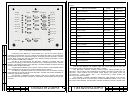
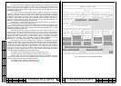
The ЭМ-1212-1 control module (Fig.1) provides manual command input for the
ЭМ-1209-1 controller with the buttons mounted on the front panel and LED indication of
execution of the following commands:
- switching on and off of any of the 20 TVDs of the TV-complex with buttons GROUP1-
GROUP5, CHANNEL1-CHANNEL4, OFF.
- enabling the night mode of the KT-257 TV-camera with button NIGHT MODE;
- control of the selected ТМ-1220-1 optical TV-module with button TEST ON.
- indication of location of faulty TVDs under servicing or servicing completion with
buttons TVD TO CHECK and TVD FROM CHECK.
- testing LEDs and buttons of the ЭМ-1212-1 control module with button TEST of the
ЭМ-1212-1.
P. P.
12
11