


Rev. P. Dokument N Signature Data
ТЭ3.623.912-03РЭ
ТЭ3.623.912-03РЭ
Rev. P. Dokument N Signature Data
Size А3 /А4
Signature and Data
Invent N of doubl
Subst. of invent N
Signature and Data
Invent N of orig.
1.1.2 Main Technical Parameters
The device has the following main technical parameters:
- number of video signal inputs - 21;
- number of video signal outputs - 4;
- swing of input and output video signals - (1 ± 0,3) V;
- load resistance in video signal circuit - (75 ± 5%) Ω;
- video channel bandwidth, at least 7,3 MHz;
- scanning - interlaced, 625 lines, 25 frames a second;
- number of RCLI channels for data exchange with the TM1215-4 control module and
ТМ-1213 terminal module - 4;
- number of RCLI channels for data exchange with the ТМ-1304 combine modules - 6;
- lock mode - autonomous;
- number of DGP output signals - 6;
- two independent channels for receiving chronometrical information from device
"Гном-2МЭ";
- supply voltage - three-phase, from 180 to 231 V;
- feeding voltage frequency - (50 ± 1) Hz;
- power consumption - no more than 500 VA, including total power consumption of
external load not exceeding 350 VA;
- continuous operation time - 5000 h;
- overall dimensions – no more than 1722 x 360 x 629 mm;
- weight, maximum - 125 kg.
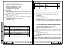
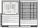
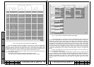
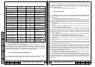
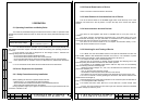
1.1.3 Device Contents
The device includes the parts shown in Table 1.
Table 1
Designation Code Part Name Qty.
ТЭ2.045.544 ВС-2 Television monitor 1
ТЭ2.067.408 ФСП-3В Interference rejection filter 6
ТЭ2.072.492 ЭМ-1211 Diagnostics module 1
ТЭ2.201.769 ЭМ-1213 Power supply unit 3
ТЭ2.242.434-01 ЭМ-1204-1 Videoswitch module 1
ТЭ2.242.435-01 ЭМ-1205-1 Videoswitch module 1
ТЭ2.275.261 ЭМ-1242 Interface unit 1
Table 1 (continued)
Designation Code Part Name Qty.
ТЭ3.057.439-01 ЭМ-1209-1 Controller 1
ТЭ3.679.117-01 ЭМ-1212-1 Control module 1
ТЭ5.883.022 Assembly unit 1
1.1.4 Device Structure and Operation
Modules and units of the device form several functional systems, that are parts of the
corresponding systems of the TV-complex. This functional systems are listed below:
- system providing generation, processing and displaying of video signals;
- genlocking system;
- control system;
- automated checkout system;
- chronometrical information input system;
- power supply system;
- auxiliary communication system.
Most modules included by the device contain units that are parts of different systems.
The description of the device and operation thereof refers to elements in the
ТМ-1104-3 ТЭ3.623.912-03Э4 TV-module electric connection diagram and the
ТЭ1.133.110-02Э6 TV-complex general electric diagram.
1.1.4.1 Video Signal Generation, Processing and Displaying System
The system of video signal generation, processing and displaying provides:
- “mirror” rotation of the image arriving from the KT-257 TV-camera;
- multiplexing of 21 input video signals to five outputs;
- generation of a video signal for displaying information on the TV-comlex state on the
ВС-2 TVM;
- displaying of video information from the TVDs of the TV-complex on the screen of the
ВС-2 TVM.
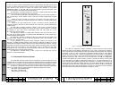
The device contains three main modules of the video signal generation, processing
and displaying system:
- videoswitch module, ЭМ-1204-1 (А31);
- videoswitch module, ЭМ-1205-1 (А32);
- ВС-2 television monitor (А11);
- ЭМ-1211 diagnostics module (А21) that generates the video signal containing data
on the TV-complex state.
The ЭМ-1205-1 videoswitch module converts the inverse image from the KT-257
TV-camera (created by the lens of pull-out optical device “Сигнал-3”) to an erect image. The
ЭМ-1205-1 videoswitch module provides several modes of image rotation: by line, by frame
and by both at the same time. The rotation mode is set by parallel binary code that is used for
remote control. The code comes from the ЭМ-1204-1 videoswitch module.
P. P.
7
8