


Rev. P. Dokument N Signature Data
ТЭ3.623.912-03РЭ
ТЭ3.623.912-03РЭ
Rev. P. Dokument N Signature Data
Size А3 /А4
Signature and Data
Invent N of doubl
Subst. of invent N
Signature and Data
Invent N of orig.
The video signal from the KT-257 TV-camera comes to connector X1 of the device
and then – to the input of the ЭМ-1205-1 videoswitch module. The ЭМ-1205-1 videoswitch
module contains a DAC, an ADC and a PLIC. The ADC performs conversion of the analog
video signal into a digital one. Then, the PLIC provides writing of the data into the internal
RAM and reading the content of the RAM in an inverse order thereby performing the image
rotation required. The rotation process is initiated on a remote control command. From the
output of the PLIC the digital data come to the DAC that does the conversion into an analog
output video signal.
The ЭМ-1204-1 videoswitch module performs multiplexing of 21 input video signals to
five outputs in accordance with remote control commands that come from the ЭМ-1209-1
controller via RCLI lines.
The ЭМ-1204-1 videoswitch module contains an analog matrix multiplexer providing
commutation of 24 input signals to 6 outputs. The device employs only 21 inputs and five
outputs. The matrix multiplexer is driven by a built-in microcontroller (MC) receiving
commands from the ЭМ-1209-1 controller.
The video signal from the output of the ЭМ-1205-1 videoswitch module comes to input
1 of the ЭМ-1204-1 videoswitch module. The signals from the TVDs of the TV-complex are
connected to inputs 2 to 20. "Video Input 21" of the ЭМ-1204-1 videoswitch module is
reserved and not used in the TV-complex. The output video signals of the ЭМ-1204-1
videoswitch module are assigned as follows:
"Video Output 1" via connector X22 of the device comes to TVM ВС-2-1 No.1 of the
TV-complex (first CP of TV-complex);
"Video Output 2" via connector X23 of the device comes to TVM ВС-2-1 No.2 of the
TV-complex (second CP of TV-complex);
"Video Output 3" via connector X24 of the device comes to the ВС-1-1 No.1 of the TV-
complex (third CP of the TV-complex);
"Video Output 4" comes to connector X25 of the device and is not used in the TV-
complex;
"Video Output 5" comes to the video input of the ЭМ-1211 diagnostics module and
then - to the ВС-2 TVM.
The ЭМ-1211 diagnostics module performs switching between video signals for the
ВС-2 TVM coming from the ЭМ-1204-1 videoswitch module and a diagnostics signal that is
generated by the ЭМ-1211 diagnostics module by itself.
Commutation of video signals is done by pressing the buttons on the front panel of the
ЭМ-1211 diagnostics module. By pressing button SELECT the video signal from the
ЭМ-1204-1 videoswitch module (from the TVD chosen on the
ЭМ-1212-1 control module) is
connected to the ВС-2 TVM. Pressing button ENTER provides connection of the video signal
formed in the ЭМ-1211 diagnostics module, containing data on the TV-complex state, to the
screen of the ВС-2 TVM.
1.1.4.2 Genlocking System
The genlocking system provides centralized synchronization of all the TVDs of the
complex by forming DGP signals on the six output connectors of the device. The DGP signal
constitutes a pulse sequence with a swing of 3 V, frequency of 15625 Hz and duration of
5 µS. Every 625-th pulse has a duration of 12 µS. The centralized synchronization reduces
the mutual interference level and simplifies video signal processing.
The main unit of the genlocking system is the EM-1209-1 controller. The PLIC of the
unit forms the DGP signal basing on clock pulses of a quartz oscillator and supplies it to the
six DGP outputs via a buffer amplifier. This signals are fed to connectors X26-X31 of the
device and finally arrive to the TM-1304 combined modules. One DGP output (connector
X31) is reserved and not used in the TV complex.
1.1.4.3 Control System
The functional control system (CS) is formed by the ЭM-1209-1 controller (A33) along
with microcontrollers and microprocessors of the main device modules interconnected via
RCLI lines. The ЭM-1209-1 controller constitutes a dedicated computer performing the main
control functions of the TV complex. The microcontrollers and microprocessors that are parts
of the ЭM-1204-1 videoswitch module (А31), ЭМ-1211 diagnostics module (А21), ЭM-1212-1
control module (А22), and ЭM-1242 interface unit (А23) perform local control functions.
The control system provides:
- communication with the TM-1215-4 control modules and the TM-1230 control module
of the TV complex CPs to receive control instructions from the module buttons;
- input of control instructions from the ЭM-1212-1 control module, that is a part of the
device, during the TV complex operation check.
- processing of control instructions and output of instructions to the execution units of
the device and other modules of the TV complex to provide power supply and control of the
TVDs, correction and commutation of video signals, centralized genlocking and video
recording.
- receiving and analysis of replies of execution units and indication of instruction
fulfillment results;
- preparation and output of data about the state of the TV-complex to the automatic
checkout system (ACS).
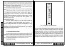
The ЭM-1209-1 controller is the main control element of both the device control
system and the whole TV complex. The working software of the controller is written to ROM
and provides control of the TV complex via serial duplex communication channels. The
ЭM-1209-1 controller incorporates a power supply supervisor and a watchdog timer,
controlling the working program execution and automatically resetting the system in case of a
fault. The ЭM-1209-1 controller provides 14 serial duplex interface channels (RCLI) and an
RS-232 channel. The working program can be reset by pressing the RESTART button,
mounted on the front panel of the controller. The ЭM-1209-1 controller is installed on the third
floor of the device in the rightmost row (see Appendix B, pos.13). To the left of that the two
ЭM-1209-1 controllers of the BSP are installed.
The modules that are parts of the device as well as other modules included by the
TV-complex are controlled via RCLI channels.
The RCLI channels have the following parameters:
- loop-type channel, duplex, four-wire, two wires are used for output datastreams (data
transmission lines) and two wires are used for input datastreams (data reception lines);
- data transmission and reception circuits are galvanically decoupled;
- baud rate - 19200;
- number of data bits - 8;
- number of stop bits – 1;
- LSB is transferred first;
- pause, stop bit and logic one are transferred as current from 0 to 1 mA;
- start bit and logic 0 are transferred as current from 15 to 25 mA;
P. P.
10
9