


Rev. P. Dokument N Signature Data
ТЭ3.623.912-03РЭ
ТЭ3.623.912-03РЭ
Rev. P. Dokument N Signature Data
Size А3 /А4
Signature and Data
Invent N of doubl
Subst. of invent N
Signature and Data
Invent N of orig.
KT-257 TV-camera. If button PERISCOPE NIGHT is pressed again the night channel of the
KT-257 TV-camera will be switched on in at least 5 s since the day channel switch-on. If the
night channel of the KT-257 TV-camera has already been switched on and button
PERISCOPE NIGHT on the other ТМ-1215-4 control module is pressed, the signal of the
night channel will be connected to the TVM without delay.
ЭМ-1211
The ЭМ-1209-1 controller prohibits the TM-1215-4 control module with the lowest
priority from execution of the following control commands:
TROUBLE
- input a test into the TM-1220-1 optic-television module if it was already switched on
from the ЭМ-1212-1 control module or from a ТМ-1215-4 control module having a higher
priority;
ENTER
- switch on the day channel of the KT-257 TV-camera if the night channel was
switched on from the ЭМ-1212-1 control module or from a ТМ-1215-4 control module having
a higher priority;
- switch on the night channel of the KT-257 TV-camera if the day channel was
switched on from the ЭМ-1212-1 control module or from a ТМ-1215-4 control module having
a higher priority;
SELECT
The ЭМ-1209-1 controller prohibits to switch on the KT-257 TV-camera and the
TM-1220-1 optic-television modules from the ТМ-1215-4 No.3 control module. If an attempt
at switching on this units occurs, light-emitting diode NO TVD lights up on the
ТМ-1215-4 No.3 control module.
RESTART
The ЭМ-1209-1 prohibits to enable video recording from the ТМ-1215-4 No.2 и
ТМ-1215-4 No.3 control modules. On pressing button RECORD ON on this modules light-
emitting diode NO CTRL lights up.
The ЭМ-1209-1 prohibits controlling the ДЕ-118-1 VRD from the front panel of the
TM-1230 control module, if prior to that the registration mode was activated on the
ТМ-1215-4 No.1 control module.
A TVD generating an abnormal image undergoes checking and servicing. The
ЭМ-1209-1 controller provides indication of the servicing mode from the ЭМ-1212-1 control
module with recording the number of the ТМ-1215-4 control module from which the TVD was
forwarded for servicing. During this the power supply remains connected to the TVD and the
video signal of the TVD comes to the corresponding TVM. On enabling the TVD under
servicing from any of the ТМ-1215-4 control modules or ЭМ-1212-1 control module light-
emitting diode TVD TO CHECK lights up thereon.
The
ЭМ-1209-1 controller allows to take a TVD out of servicing only from the
ЭМ-1212-1 control module panel.
1.1.4.4 Automated Checkout System
The automated checkout system (ACS) is intended for continuous supervision over
the state of all the modules and units of the device, gathering of data on the state of units and
modules of the TV-complex. The ACS analyses the incoming data and indicates the state of
the TV-complex modules and units by means of the LEDs and the screen of the ВС-2 TVM.
The ЭМ-1211 diagnostics module (А21) is the main module of the ACS of the device
and the TV-complex also. The ACS comprises the following modules of the device:
- ЭМ-1212-1 control module (А22);
- ЭМ-1209-1 controller (А33);
- ВС-2 television monitor (А11).
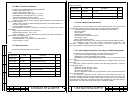
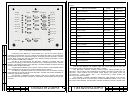
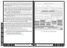
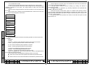
Fig. 2 – Front panel of ЭМ-1211 diagnostics module.
The ЭМ-1211 diagnostics module constitutes a special computer whose working
software is written into the ROM by Manufacturer. It has a built in power supply supervisor
and a watchdog timer automatically controlling the working program execution and resetting
the system in case of a fault. The ЭМ-1211 diagnostics module includes a video adapter
forming the video signal and a switch connecting either the external signal or the adapter
signal to the common output. The 55-channel ADC measures the incoming d.c. voltages from
minus 30 to plus 30 V with a ratio error of no more than 0,2%. The ЭМ-1211 diagnostics
module has an RS-232 and a RCLI interface channels. There are five buttons and one LED
on the front panel of the ЭМ-1211 diagnostics module (Fig.2). The LED indicates a fault in
the TV-complex. Button ENTER outputs the ACS frame No.1 on the ВС-2 TVM screen. The
arrow buttons allow switching between frames of the ACS. Button SELECT switches the
video signal from the ЭМ-1204-1 videoswitch module to the screen of the ВС-2 TVM. Button
RESTART forces reset of the working program. The ЭМ-1211 diagnostics module is installed
on the second floor of the device in the leftmost row (Fig. B1, pos.3).
P. P.
16
15