


Rev. P. Dokument N Signature Data
ТЭ3.623.912-03РЭ
ТЭ3.623.912-03РЭ
Rev. P. Dokument N Signature Data
Size А3 /А4
Signature and Data
Invent N of doubl
Subst. of invent N
Signature and Data
Invent N of orig.
Remedy – replace the BC-2 TVM with the serviceable one from the BSP.
2.3.3.7 No image from several TVDs on the TVM screens of all the CPs. The ACS
indicates that the TVDs and the ЭМ-1204-1 VS commutation module are fault-free.
Cause – the VS matrix switch in the ЭМ-1204-1 VS commutation module is out of
order.
Remedy – replace the ЭМ-1204-1 VS commutation module with the serviceable one
from the BSP.
2.3.3.8 No image from the КТ-257 TV-camera on the TVM screens of several CPs.
The ACS indicates the KT-257 TV-camera and the ЭМ-1205-1 VS commuatation module are
fault-free.
Cause - the ЭМ-1205-1 VS commutation module is out of order.
Remedy – replace the ЭМ-1205-1 VS commutation module with the serviceable one
from the BSP.
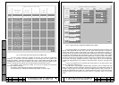
2.3.3.9 According to the ACS, one of the 27 V output voltages in one of the ЭМ-1213
power supply units is missing. The “27 V” LED on the front panel of the ЭМ-1213 power
supply does not light. After replacing the ЭМ-1213 power supply unit with the serviceable one
from the BSP the trouble persists.
Cause – one of the six ФСП-3В filters is out of order.
Remedy – using the ACS determine exactly the faulty ФСП-3В filter by missing +27V
voltage as follows:
- no "+27 ВI" from the output of the ЭМ-1213 No.1 (A61) – fault in А2 (designations of
the ФСП-3В filters is shown in diagram ТЭ3.623.912-03 Э4);
- no "+27 VII" from the ЭМ-1213 No.1 (A61) - fault in А3;
- no "+27 VI" from the ЭМ-1213 №2 (A71) - fault in А4;
- no "+27 VII" from the ЭМ-1213 №2 (A71) - fault in А5;
- no "+27 VI" from the ЭМ-1213 №3 (A72) - fault in А6;
- no "+27 VII" from the ЭМ
-1213 №3 (A72) - fault in А7.
Replace the faulty filter with the serviceable one of the DSP.
2.3.3.10 The ACS indicates a fault in some module or unit of the device because the
feeding voltage of this module or unit exceeds the tolerance bounds. Even so, the faulty
module or unit continues to operate normally. After replacing the faulty module with the
serviceable one from the BSP, the ACS indicates the same fault.
Cause – the ЭМ-1211 diagnostic module is out of repair.
Remedy – replace the ЭМ-1211 diagnostics module with the serviceable one from the
BSP.
2.3.3.11 No chronometrical information from both the channels of the "Гном-2МЭ"
device. The latter operates normally. The ACS indicates that the ЭМ-1242 interface unit is
fault-free.
Cause - the ЭМ-1242 interface unit failure as per the interface with device
"Гном-2МЭ".
Remedy - replace the ЭМ-1242 interface unit with the serviceable one from the BSP.
2.3.3.12 After replacing a faulty module with a serviceable one, make a record in TV-
complex logbook ТЭ1.133.110-02ФО.
2.3.4 Switching the Device off
To switch the device off press the OFF button on the BC-2 TVM.
Move the toggle POWER switch on the assembly into the off position. Make sure that
the phase voltage indicators do not light.
Close the drop cover on the assembly device. Close the door of the cabinet.
2.3.5 Safety Precautions during Usage of Device
The device is fed with a voltage of 220 V that is dangerous for life.
Never replace fuses, remove the included modules or unlink the connectors of
external cables when the device is energized.
If a faulty module is detected, it should be replaced only after switching-off the power
supply of the device by moving the POWER toggle switch into the off position.
Prior to replacement of the ФСП-3В filter, the POWER switch of the device and all the
switches on the ЩР-03 switchboard must be moved in the off position.
2.4 Measures under Emergency Conditions
Under emergency conditions in the place of device installation, e.g. appearance of
smoke, fire, a danger of flood, de-energize the device by moving the POWER toggle on the
ЩР-03 switchboard in the off position.
If an emergency situation arises in the place of installation of the ТМ-1304 combined
modules, TVDs or ТМ-1215-4 control modules of the TV-complex, the conditions there
should be observed on as long as possible.
Under the danger of failure or in case of some TV-complex equipment failure de-
energize the corresponding units and modules.
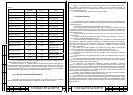
The feeding voltage can be switched off by removing the fuses on the fuse panel of
the fifth floor of the device. In case of module or unit failure under emergency conditions the
following fuses must be removed:
- in case of the ТМ-1304 No.1 combined module failure - F1, F2;
- in case of the ТМ-1304 No.2 combined module failure - F3, F4;
- in case of the ТМ-1304 No.3 combined module failure - F9, F10;
- in case of the ТМ-1304 No.4 combined module failure - F5, F6;
- in case of the ТМ-1304 No.5 combined module failure - F7, F8;
- in case of failure of the ТМ-1213 terminal module, ДЕ-118-1 VRD, ТМ-1215-4 No.1
and ТМ-1215-4 No.2 control modules - F13, F14;
- in case of the ТМ-1215-4 No.3 control module failure - F15, F16.
The said fuses can blow-out by themselves. In this case, do not replace them until the
effects of the emergency situation are not removed.
In case of emergency evacuation of the operating personnel switch the device off by
moving the POWER toggle on the ЩР-03 switchboard in the off position.
P. P.
34
33