


Rev. P. Dokument N Signature Data
ТЭ3.623.912-03РЭ ТЭ3.623.912-03РЭ
Rev. P. Dokument N Signature Data
Size А3 /А4
Signature and Data
Invent N of doubl
Subst. of invent N
Signature and Data
Invent N of orig.
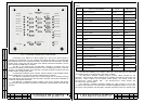
- by turns, from top to bottom and from left to right, the green LEDs installed near the
buttons will light up and then go out;
Such lighting-up of all the LEDs means that the LEDs indicating the state of the TV-
complex are serviceable.
After completion of testing lighting-up of the LEDs, no LED under the TROUBLE
inscription should be lit.
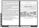
2.2.5.6 Press the ENTER button on the ЭМ-1211 diagnostics module. Frame No.1 of
the ACS, "STATE OF МТК-110МЭ", should appear on the BC-2 TVM screen. All the
modules, units and fuses in this frame should be in on-state and should not blink.
Press the "←" button on the ЭМ-1211 diagnostics module. Frame No.3 of the ACS,
"MODULE FEEDING VOLTAGES", should appear on the BC-2 TVM screen. The horizontal
lines showing the values of the supply voltages should be between the marks corresponding
to the minimum and maximum values.
Press the SELECT button on the ЭМ-1211 diagnostics module. The ACS frame will
disappear from the screen of the BC-2 TVM and the screen will display the VS from the TVD
activated from the ЭМ-1212-1 control module.
2.2.5.7 Check operation of the TVDs and viewing the signals from those. This is done
by pressing the GROUP1 button and then – the CHANNEL1-CHANNEL4 buttons. The
screen of the TVM should display the image from the TVD corresponding to the selected
channel and group. Then repeat the same for groups 2 – 5 for all the channels of these
groups and make sure that image from each of the TVDs is present. Press the OFF button to
switch the TVDs off.
2.2.5.8 Close the cover of the assembly unit. Close the door of the device by putting
the lock handles into the "LK" position and tighten the clamping nuts by rotating them
clockwise.
2.3 Usage of Device
2.3.1 Personnel Operation during Intended Use of Device
After enabling and testing the device does not require any servicing by special
personnel.
The device begins to execute its main functions in 1 s. after switching on the POWER
toggle switch on the assembly unit regardless of operations during testing the device.
2.3.2 Checking Operability of Device
The operability control is done in compliance with items 2.2.5.2 - 2.2.5.8. If the toggle
switch on the assembly unit is on do not switch it again.
2.3.3 Possible Troubles and Remedies thereof
Repair of the device is performed by replacing the faulty modules with serviceable
ones included into the BSP and DSP.
For detection of faults in the device the ACS should be used.
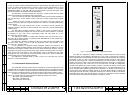
Lighting of a red LED of the TROUBLE group on the ЭМ-1212-1 control module front
panel near the code of a module or a group of modules testifies to malfunction of those.
For more exact location of the faulty module, unit or fuse switch on the BC-2 TVM and
press the ENTER button on the front panel of the ЭМ-1211 diagnostics module. ACS frame
No.1, "STATE OF МТК-110МЭ", will appear on the screen of the BC-2 TVM. The codes of
faulty modules, units and fuses of the device will be blinking. Replace these modules, units
and fuses with good ones from the BSP or DSP.
The ACS permits to find the most probable troubles in the device.
For detection of less probable troubles follow the recommendations given in items
2.3.3.1 - 2.3.3.11.
2.3.3.1 After pressing the TEST button on the ЭМ-1212-1 control module one or
several LEDs do not light up.
Cause – the ЭМ-1212-1 control module is out of repair.
Remedy – replace the ЭМ-1212-1 control module with the serviceable one from the
BSP.
2.3.3.2 Several TVDs of the same group or of the same channel in several groups can
not be switched on from the ЭМ-1212-1 control module. The corresponding LED near the
button does not light up.
Cause – the button or the PLIC of the ЭМ-1212-1 control module are out of order.
Remedy – replace the ЭМ-1212-1 control module with the serviceable one from the
BSP.
2.3.3.3 One group or one channel of the ЭМ-1212-1 control module does not switch
off by pressing the OFF button. In this case, the LED near this button goes out only when the
button is pressed and lights up again if the button is released.
Cause – the button or the PLIC of the ЭМ-1212-1 control module are out of order.
Remedy – replace the ЭМ-1212-1 control module with the serviceable one from the
BSP.
2.3.3.4 When the ON button of the BC-2 TVM is pressed the LED near the ON button
does not light and the BC-2 TVM does not work. At the same time the "27V" LED lights.
Case – fault in the ЭМ-1239 power supply unit that is a part of the BC-2 TVM.
Remedy – replace the ЭМ-1239 power supply unit with the serviceable one from the
BSP.
2.3.3.5 There is no image synchronization on the screen of the BC-2 TVM.
Cause – fault in the ЭМ-1229 video adapter that is a part of the BC-2 TVM.
Remedy – replace the ЭМ-1229 video adapter with the serviceable one from the BSP.
2.3.3.6 There is no image on the screen of the BC-2 TVM when signals from a TVD or
from the ЭМ-1211 diagnostics module are commutated to the TVM screen. The image does
not appear even after pressing the RESTART button on the ЭМ
-1211 diagnostics module.
Cause No.1 – fault in the ЭМ-1211 diagnostics module as per signal commutation.
Remedy – replace the ЭМ-1211 diagnostics module with the serviceable one from the
BSP.
Cause No.2 − fault in the ЭМ-1229 video adapter that is a part of the BC-2 TVM.
Remedy – replace the ЭМ-1229 video adapter with the serviceable one from the BSP.
Cause No.3 – the BC-2 TVM is out of repair.
P. P.
32
31