


Rev. P. Dokument N Signature Data
ТЭ3.623.912-03РЭ
ТЭ3.623.912-03РЭ
Rev. P. Dokument N Signature Data
Size А3 /А4
Signature and Data
Invent N of doubl
Subst. of invent N
Signature and Data
Invent N of orig.
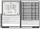
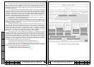
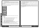
Fig. 1 – Front panel of the ЭМ-1212-1 control module.
Functioning of the ЭМ-1212-1 control module as a part of the control system is
provided by microcontroller CS, PLIC, interface and buttons with LEDs. The microcontroller
(MC) together with the PLIC inquires the buttons. On request from the ЭМ-1209-1 controller
the MC forms a reply array with the codes of the buttons pressed and transfers it via the
RCLI channel to the ЭМ-1209-1 controller.
The MC of CS receives from the ЭМ-1209-1 controller a command array with
instructions for lighting up the LEDs and switches on the corresponding LEDs by means of
the PLIC. The working program of the ЭМ-1209-1 controller analyses the button state and
decides whether to light up the LEDs.
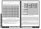
Correspondence between group numbers, channel numbers, TVD installation places
and the designation on the ТМ-1215-4 control module is shown in Table 2.
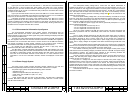
The ЭМ-1211 diagnostics module has a microprocessor and an interface receiving
arrays with data on the CS state from the ЭМ-1209-1 controller and provide visualization of
the data in video frames of the ACS.
The ЭМ-1204-1 videoswitch module contains a MC and an interface that receive
instructions from the ЭМ-1209-1 controller for commutation of video signals and control their
execution.
Table 2
Group-
channel
Place of TVD installation
Video signal
source
Designation on
ТМ-1215-4
1-1
Device ″Сигнал-3″
КТ-257 PERISCOPE
1-2
Fore end, − 6 frame
ТМ-1220-1 FE –6FR
1-3 1 room, 1 deck, starboard side Неотон-08-2 1R 1D STB
1-4 1 room, 2 deck Неотон-08-1 1R 2D
2-1 1 room, 1 deck, port side Неотон-08-1 1R 1D PS
2-2 Superstructure, 20 frame ТМ-1220-1
SUPRSTR 20FR
2-3 3 room, 1 deck Неотон-08-2 3R 1D
2-4 3 room, 3 deck Неотон-08 3R 3D
3-1 4 room, 1 deck Неотон-08-2 4R 1D
3-2
BF, winch automated communication
system
ТМ-1220-1 WINCH ACS
3-3 4 room, 2 deck, starboard Неотон-08-1 4R 2D STB
3-4 4 room, 2 deck, port side Неотон-08-1 4R 2D PS
4-1 5 room, port side Неотон-08-2 5R PS
4-2 5 room, starboard Неотон-08-2 5R STB
4-3 Pod, winch sonar system ТМ-1220-1 WINCH SS
4-4 4 room, 2 deck, PCS Неотон-08 4R 2D PCS
5-1 6 room, 1 deck, aft Неотон-08-1 6R 1D A
5-2 6 room, 1 deck, fore Неотон-08-1 6R 1D F
5-3 Tiller compartment Неотон-08 TC
5-4 Pod, 108 frame ТМ-1220-1 POD 108FR
ЭМ-1212-1
TROUBLE
GROUP CHANNEL TVD CONTROL TROUBLE
ЭМ-1204-1 ТМ-1304 N1
ЭМ-1205-1 ТМ-1304 N2
ЭМ-1209-1 ТМ-1304 N3
ЭМ-1242 ТМ-1304 N4
ЭМ-1213 N1 ТМ-1304 N5
ЭМ-1213 N2
ЭМ-1213 N3 ТМ-1215-4 N1
ТМ-1215-4 N2
ТМ-1215-4 N3
OFF
The ЭМ-1242 interface unit contains a MC and a PLIC that form an array with
chronometrical data on request from the ЭМ-1209-1 controller.
The ЭМ-1209-1 controller working program provides various priorities for the
ЭМ-1212-1 and ТМ-1215-4 control modules as per enabling and control of the TVDs. The
ЭМ-1212-1 control module has the highest control priority. The second comes the
ТМ-1215-4 No.1 control module, then - the ТМ-1215-4 No.2 control module and
ТМ-1215-4 No.3 control module.
The ЭМ-1209-1 prohibits accidental enabling the night channel of the KT-257
TV-camera in the day time. On the first press on button PERISCOPE NIGHT on any of the
ТМ-1215-4 control modules, the ЭМ-1209-1 controller will switch on the day channel of the
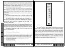
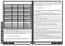
ТМ-1213
МТК-110МЭ ДЕ-118-1
FUSE
1
2
3
4
5
NIGHT
MODE
1
TEST
ON
2
TVD
TO
CHECK
3
4
TVD
FROM CHECK
TEST ЭМ-1212-1
P. P.
14
13