


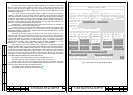

Rev. P. Dokument N Signature Data
ТЭ3.623.912-03РЭ ТЭ3.623.912-03РЭ
Rev. P. Dokument N Signature Data
Size А3 /А4
Signature and Data
Invent N of doubl
Subst. of invent N
Signature and Data
Invent N of orig.
The ADC of the ЭМ-1211 diagnostics module samples the d.c. voltages from the three
ЭМ-1213 power supply units, outputs of fuses F1-F16, power supply units built into the
device modules and control voltages +27V from connectors X38 and X39. The ЭМ-1211
diagnostics module measures these voltages and finds faulty modules that fall out of the
corresponding tolerances.
Via a RCLI channel the diagnostics module receives data from the ЭМ-1209-1
controller on the state of the TV-complex units and modules. This information is prepared
during data exchanges via the RCLI channels and contains data on the presence of feeding
voltages and video signals, character of data exchanges between different modules of the
TV-complex, state of the TVDs, VRDs and the ТМ-1215-4 control modules. The ЭМ-1211
diagnostics module transfers data for light indication of faulty units and modules to the
ЭМ-1212-1 control module via a separate RCLI channel.
The ЭМ-1212-1 control module forms three video frames of the ACS for indication of
the TV-complex state on the screen of the ВС-2 TVM.
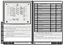
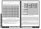
The ACS frame No.1, "STATE OF МТК-110МЭ" (Fig.3), is formed on pressing button
ENTER. In this frame enabled modules and units are shown as their codes against a light
background, disabled – as theirs codes against a dark background and faulty ones – as their
codes against a blinking background.
The states of the main modules and fuses F1-F16 of the device are shown in the
upper part of the frame. The state of the ТМ-1215-4 No. 1- ТМ-1215-4 No.3 control modules
is shown below. The ТМ-1215-4 No.1 interacts with the ТМ-1213 terminal modules having
the ЭМ-1240 interface unit therein and the ДЕ-118-1 VRD. This devices are grouped
together in the frame. Near the ДЕ-118-1 VRD its state is shown. The following states of the
VRD are shown: "STOP", "OFF", "RECORD", "PLAY", "PAUSE", "REWIND <<", "FAST
FORWARD >>", "NO VIDEO CASSETTE", "VRD TROUBLE", "NO CONTROL".
The five columns of the units related to the ТМ-1304 No.1 - ТМ-1304 No.5 combined
modules are shown below. There are the states of the ЭМ-1202 control and synchronization
modules, ЭМ-1203 video amplifier modules, БПИ-183-
а power supply units incorporated by
the ТМ-1304 combined modules shown togethes with the states of the four TVDs connected
to each ТМ-1304 module depending on their location. In the lower area of the frame are
shown the data and time that are received by the ЭМ-1242 interface unit from device
"Гном-2МЭ". In case of signal absence in any of the channels for exchange with device
"Гном-2МЭ" dashes are displayed instead of date and time.
The number of the ACS frame No.2 is shown in the right lower corner.
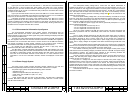
The ACS frame No.2, "STATE OF МТК-110МЭ TVDs" is shown in Fig.4.
The left column, "N", shows the numbers (group-channel) of the TVDs. The group
number is the number of the ТМ-1304 combined module. The channel number corresponds
to the TVD connected to this ТМ-1304 combined module.
The "NAME" column contains the location of the TVD.
The "CODE" column contains the code of the TVD.
STATE OF МТК-110МЭ
ТМ–1104–3
Fig.3 –ACS Frame No.1 "STATE OF МТК-110МЭ".
17
18
ЭМ–1212-1 ЭМ–1242 ЭМ–1204-1 ЭМ–1205-1
ЭМ–1209-1
ЭМ–1213 N1
ЭМ–1213 N2
ЭМ–1213 N3
F1 F2
F3
F4
F5
F6 F7 F8
F9
F10
F11
F12
F13
F15
F14
F16
ЭМ–1211
ТМ–1215–4 N1
ТМ–1215–4 N2
ТМ–1215–4 N3
ТМ–1213
ЭМ–1240
ДЕ–118–1=> NO VIDEO CASSETTE
ТМ–1304 N1
ТМ–1304 N2
ТМ–1304 N3
ТМ–1304 N4
ТМ–1304 N5
ЭМ–1202 ЭМ-1202 ЭМ-1202 ЭМ-1202
ЭМ-1202
ЭМ-1203
ЭМ-1203
ЭМ-1203
ЭМ-1203
ЭМ-1203
БПИ–183-а
БПИ-183-а БПИ-183-а
БПИ-183-а
БПИ-183-а
PERISCOPE 1R 1D PS
4R 1D
5R PS
6R 1D A
FE–6FR SUPRSTR 20FR
WINCH ACS
5R STB
6R 1D F
1R 1D STB
3R 1D
4R 2D STB
WINCH SS
TC
1R 2D
3R 3D
4R 2D PS
4R 2D PCS
POD 108FR
DATE AND TIME FROM "ГНОМ –2МЭ" DEVICE
CHANNEL 1 ЭМ-1242
CHANNEL 2 ЭМ-1242
30–01 –05 12:45:30 30–01–05 12:45:39
N1
P. P.