


Rev. P. Dokument N Signature Data
ТЭ3.623.912-03РЭ
ТЭ3.623.912-03РЭ
Rev. P. Dokument N Signature Data
Size А3 /А4
Signature and Data
Invent N of doubl
Subst. of invent N
Signature and Data
Invent N of orig.
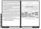
The bottom part of the cabinet is installed on an amortization base (25).
In the upper part of the cabinet under the rear cover two resilient supports (24) for
mounting the cabinet in a vertical position are installed.
On the top of the assembly unit are installed the following elements: connector XP1 for
connecting the mains voltage (220 V, 50 Hz), connectors Х32 - Х41 for interconnection
cables, auxiliary communication connector X42 and connector X43 for an RS-232 channel.
The latter is used during setup and servicing of the TV-complex.
Coaxial connectors Х1 - Х31 are mounted on the rear cover of the cabinet.
In the place of installation the cabinet on the amortization base is mounted on the
foundation and fastened from the back to the corresponding mounting elements with the
resilient supports. If the cabinet is transported through a hatch with a diameter of 594 mm the
rear supports should be temporarily removed.
The connector designation system, providing easy location of a connector basing on
its number, is given in schematic connection diagram ТЭ3.623.912-03Э4.
Cooling of the cabinet is done by natural ventilation. Cold air enters into the cabinet
through the lower grating and leaves the cabinet through the upper grating.
On the front of the lower part of the cabinet the "⊥" (bonding point) terminal is located.
This terminal must be coupled with the hull of the object of installation.
1.1.4.9 Measurement Instrumentation, Tools and Accessories
There are no special meters, tools and accessories required for work with the device.
The control over the parameters of the device is performed with the means of automated
control.
To maintain the device a special wrench (Fig.B1, pos.27) and the tools of the toolkit
included into the TV-complex BSP are used.
1.1.4.10 Marking
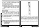
The device is identified on the nameplate. The nameplate contains the device code, its
industrial number and mass.The nameplate is fastened on the assembly unit.
1.2 Description and Operation of Device Component Parts
1.2.1 ВС-2 Television Monitor
The ВС-2 TVM is intended for displaying black-and-white images with scanning
parameters according to the broadcasting standard (interlaced scanning, 625 lines, 25
frames per second).
The ВС-2 TVM is based on the МО1-12 flat-panel LCD-module.
Technical parameters:
- power supply of the ВС-2 TVM – from d.c. network, (27±3) V;
- power consumption – 50 W, maximum;
- dimensions of screen visible area – (246×185) mm;
- ВС-2 TVM screen resolution – no less than 500 TV-lines;
- viewing angle of ВС-2 TVM screen – from 100 to 140 deg. (horizontal), from 90 to
120 deg. (vertical);
- screen brightness (in white) for the whole visible area – from 250 to 350 cd/m
2
.
- image contrast of ВС-2 TVM screen – 250:1.
- image adjustment on the screen of ВС-2 TVM is done with five buttons on the TVM
front panel via an on-screen menu.
1.2.1.1 Layout and Operation
For studying the ВС-2 TVM electrical diagram ТЭ2.045.544Э3 should be used.
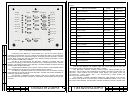
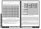
The contents of the ВС-2 TVM is given in Table 4.
Table 4
Designation Code Part Name Qty.
ТЭ2.049.458 МО1-12 Display module 1
ТЭ2.201.833 ЭМ-1239 Power supply unit 1
ТЭ3.057.444 ЭМ-1229 Video adapter 1
The following signals are applied to the ВС-2 TVM:
- feeding voltage, coming to connector X1;
- black-and-white video signal with a swing of (1,0 ± 0,3) V, coming to connector Х3.
The ВС-2 TVM is switched on and off by pressing buttons ON and OFF on the front
panel. On applying to the TVM a voltage of (27±3) V the "27 V" indicator lights up. As button
ON is pressed, the LED near the button lights up and the TVM turns on.
The ЭМ-1239 power supply unit feeding voltage to the ЭМ-1229 video adapter and
МО1-12 display module.
The ЭМ-1239 power supply unit converts the primary d.c. voltage, 27V, into secondary
stabilized d.c. voltages of 12 V and 5 V.
The ЭМ-1229 video adapter converts the black-and-white video signal with interlaced
scanning into SVGA-standard signals with non-interlaced scanning and a frame frequency of
60 Hz. These signals are input of the МО1-12 display module. At the same time, the video
adapter generates sync pulses with horizontal and frame frequencies for synchronization of
the display modules.
The MO1-12 display module is intended for displaying TV-image. The module
constitutes a LCD-panel with backlighting lamps, a control circuit and an inverter for feeding
the lamps. The LCD-panel with the control circuit and inverter is installed into a hermetic
metal case and covered with a protective glass.
As a voltage of 12 V is applied to the displaying module and the video signal is given
to the VGA-input, the luminescent backlighting lamps switch on and an image of 800×600
pixels with a refresh frequency of 60 Hz is formed on the screen.
1.2.1.2 Instructions on Switching-On and Testing
To switch on the BC-2 TVM press button ON and check if the indicator is lit.
Select the source of the TV-signal on the ЭМ-1212-1 control module. Check the
quality of the image and adjust brightness and contrast with the buttons on the TVM front
panel (see item 1.2.1.3) if necessary.
If there is no video signal, an image of chaotically lighting pixels is displayed on the
TVM screen.
P. P.
26
25