


20
7
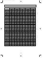
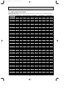
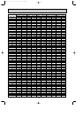
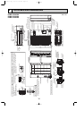
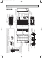
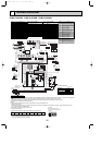
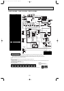
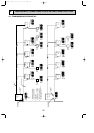
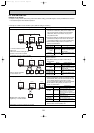
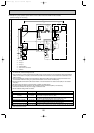
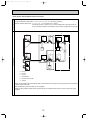
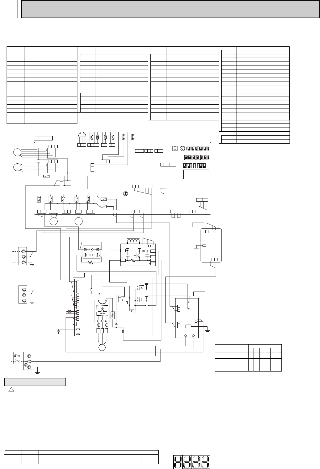
WIRING DIAGRAM
SYMBOL NAME SYMBOL NAME SYMBOL NAMESYMBOL NAME
TB1 Terminal Block <Power Supply>
TB3 Terminal Block <Transmission>
TB7 Terminal Block <Centralized Control>
MC Motor for Compressor
MF1,MF2 Fan Motor
21S4 Solenoid Valve <Four way valve>
SV1 Solenoid Valve <Bypass valve>
TH3
Thermistor <Outdoor Pipe Temperature>
TH4 Thermistor <Discharge Temperature>
TH6
Thermistor <Low Pressure Saturated Temperature>
TH7 Thermistor <Outdoor Temperature>
TH8 Thermistor <Heatsink>
63HS
High Pressure Sensor <Discharge Pressure>
63H High Pressure Switch
63L Low Pressure Switch
CB Main Smoothing Capacitor
ACTM
DCL
Active filter Module
RS Rush Current Protect Resistor
P.B. Power Circuit Board
Connection Terminal <U/V/W-Phase>
U/V/W
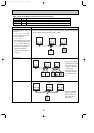
MULTI.B.
Multi Controller Board
Fuse <6.3A>
F1,F2
Fuse <3A>
F500
Switch <Display Selection>
SW1
Switch <Function Selection>
SW2
Switch <Test Run>
SW3
Switch <Model Selection>
SW4
Switch <Function Selection>
SW5
Switch <Function Selection>
SW6
Switch <Function Selection>
SW7
Switch <Function Selection>
SW8
Switch <Unit Address Selection, 1st digit>
SWU1
Switch <Unit Address Selection, 2nd digit>
SWU2
Transformer
TRANS
Digital Indicator <Operation Inspection Display>
LED1,2
LED <Power Supply to Main Microcomputer>
LED3
Connector <Multi System>
CNS1
Connector <Centralized Cotrol>
CNS2
Connector <To Noise Filter Circuit Board>
CNAC
Connector <To Noise Filter Circuit>
CNDC
Connector <To Power Circuit Board>
CN2
Connector <To Power Circuit Board>
CN4
Connector <Centralized Cotrol Power Supply>
CN40
Connector <For shorting Jumper Connector>
CN41
Connector <Thermistor>
TH3
Connector <Thermistor>
TH4
Connector <Thermistor>
TH7/6
Connector <High Pressure Sensor>
63HS
Connector <High Pressure Switch>
63H
Connector <Low Pressure Switch>
63L
Connector <Fan Motor>
CNF1,CNF2
Connector <Four-way Valve>
21S4
Connector <Bypass Valve>
SV1
Connector <For Option>
SS
Connector <For Option>
CN3D
Connector <For Option>
CN3S
Connector <For Option>
CN3N
Connector <For Option>
CN51
Relay
X501~505
M-P.B.
Connector <To Noise Filter Circuit Board>
Transmission Power Board
CN1
Connector <To Multi Controller Board>
CN2
Terminal <L/N-Phase>
TAB-S/T
Terminal <DCVoltage>
TAB-P/P1/P2
Terminal <DCVoltage>
TAB-N/N1/N2
Connector
CN2~5
N.F. Noise Filter Circuit Board
Connection Lead <L-Phase>
LI/LO
Connection Lead <N-Phase>
NI/NO
Connection Terminal <Ground>
EI
Connector
CNAC1/2
Connector
CN5
Connector
CNDC
Connector
CNAF
Inverter
IPM
Light Emitting Diodes <Inverter Control Status>
LED1
Reactor
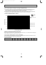
Bit
Indication
1
Compressor
operated
2
52C
3
21S4
4
SV1
5
(SV2)
6
—
7
—
8
Always lit
• During normal operation
• The LED indicates the drive state of the controller in the outdoor unit.
NOTES:
1.Refer to the wiring diagrams of the indoor units for details on wiring of each indoor unit.
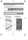
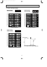
Self-diagnosis function
The indoor and outdoor units can be diagnosed automatically using the self-diagnosis switch (SW1) and LED1, LED2 (LED indication) found
on the multi-controller of the outdoor unit.
LED indication : Set all contacts of SW1 to OFF.
w1 MODEL SELECT
1: ON 0: OFF
MODELS
PUMY-P100VHM
PUMY-P125VHM
PUMY-P140VHM
• When fault requiring inspection has occurred
The LED alternately indicates the inspection code and the location
of the unit in which the fault has occurred.
SW4
123456
0
1
1
1
0
1
0
0
0
0
0
0
1
1
1
0
0
0
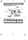
Cautions when Servicing
!
• WARNING: When the main supply is turned off, the voltage[340V] in the main capacitor will drop to 20V in approx. 2 minutes (input voltage:240V).
When servicing,make sure that LED1, LED2 on the outdoor circuit board goes out, and then wait for at least 1 minute.
• Components other than the outdoor board may be faulty: Check and take corrective action, referring to the service manual.
Do not replace the outdoor board without checking.
[Example]
When the compressor and
SV1 are turned on during cooling
operation.
12345678
1
MF1
4 5 6 7
CN2
(WHT)
CN4
(WHT)
CN51
(WHT)
1
MF2
4 5 6 7
52C
(BLK)
3
X505
1
21S4
(GRN)
3 1
SV2
(BLU)
3 1
SV1
(WHT)
SS
(WHT)
2 1
2
1
2
121
3 1
21S4
SV1
7 6 5 4 3 2 1
54321
2 1
LED3
SW6
SW2SW8SW1
SW7SW3SW4
w
1
SW5
SWU2SWU1
TRANS
LED2
88
LED1
88
1 2 1 2 1 23 4
CN3D
(WHT)
1 23
1 23
CN3S
(RED)
1 23
CN3N
(BLU)
1 23
3 1
31
CNAC
(RED)
CNS1
(RED)
CNS2
(YLW)
123
1
3
3
13
12
1
4 5 6
123 4 5 6
12 12 12 123 4 5 67
CNDC
(PIN)
CNAF
(WHT)
CN2
(WHT)
CN3
(WHT)
CN4
(WHT)
CN5
(RED)
CNAC2
(RED)
E I
CN5
(RED)
CNAC1
(WHT)
LO
NO
NILI
TABN1
TABN2
TABP2
TH8
CB
TABN
TABP
TABP1
TABT
DCL
RS
52C
ACTM
TABS
31
TH7TH6 TH3 TH463HS 63H63L
F1
F500
F2
X504
X503
X502
X501
CN102
(WHT)
CN41
(WHT)
CN40
(WHT)
4 3 2 1
4 3 2 14 3 2 1
M-P.B.
P. B.
N. F.
3 1
CN2
(WHT)
TP1
CN1
(WHT)
1 2 3 4
M1
M2
S
TB3
TO INDOOR UNIT
CONNECTING WIRES
DC 30V(Non-polar)
FOR CENTRALIZED
CONTROL
DC 30V(Non-polar)
M1
M2
S
TB7
POWER SUPPLY
~/N
AC220/230/240V 50Hz
AC220V 60Hz
TB1
MC
-
+
-
-
+
+
MULTI. B.
CNF1
(WHT)
TH7/6
(RED)
TH3
(WHT)
TH4
(WHT)
63HS
(WHT)
63H
(YLW)
63L
(RED)
CNDC
(PNK)
CNF2
(WHT)
(BRN)
(BRN)
(ORN)
(ORN)
L
N
+
-
+
+
NO FUSE
BREAKER
P
N1
L2
L1
N2
I
U
V
W
~
~
~
~
RED
WHT
BLK
PUMY-P100VHM PUMY-P125VHM PUMY-P140VHM
OC376B--1.qxp 08.1.17 1:14 PM Page 20