


67
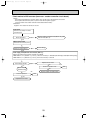
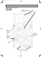
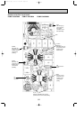
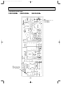
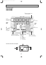
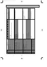
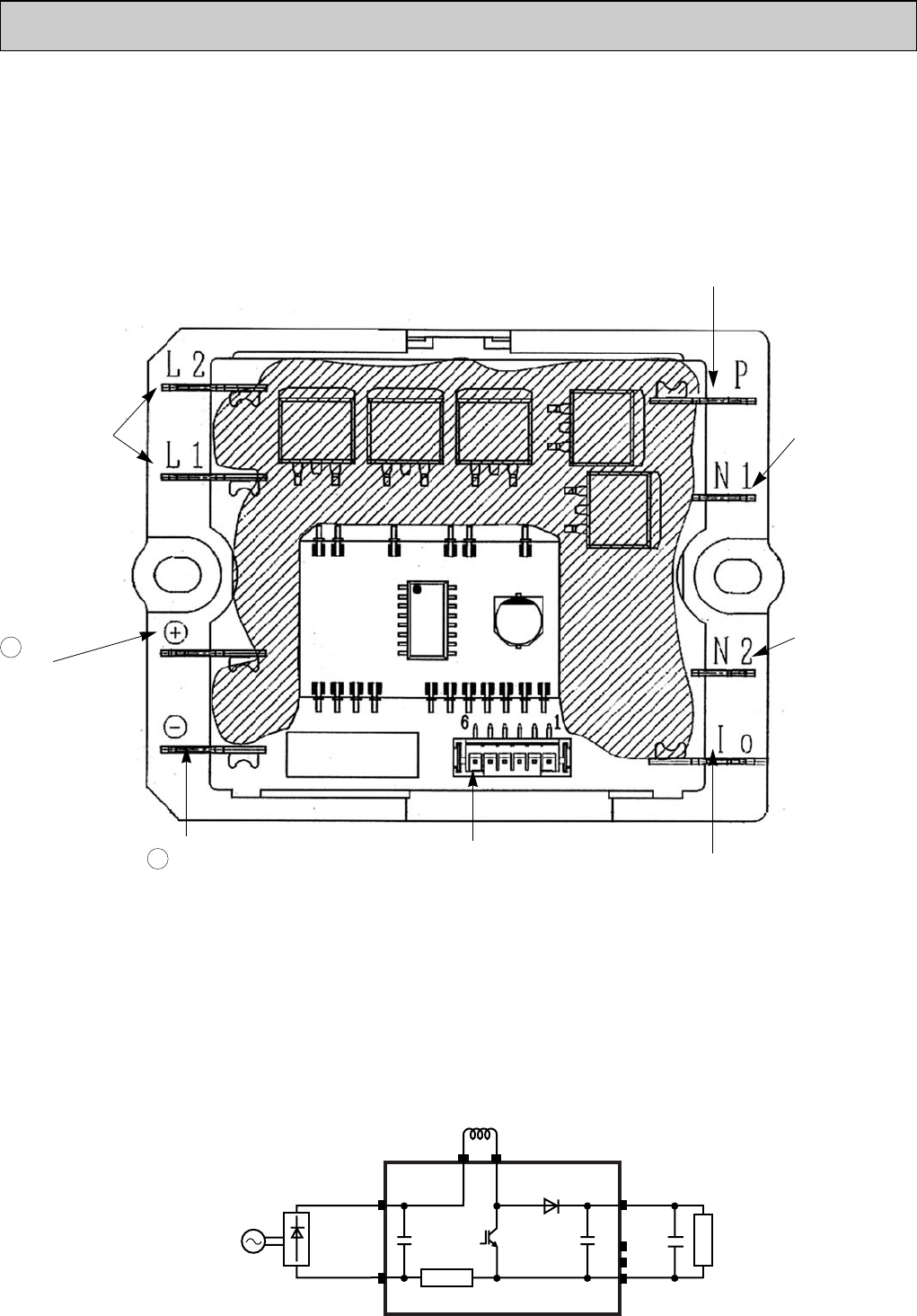
Active filter module
PUMY-P100VHMA
PUMY-P125VHMA
PUMY-P140VHMA
+
–
+
DCL
L1 L2
ACTM
P
Io
N1
N2
(+)
(- )
Load
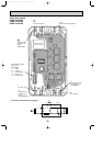
Connection and internal circuit diagram
L1, L2
Connect to the
DCL(Reactor)
Connect to the
outdoor power
circuit
board(TABP1)
N2
Non-connect
N1
Non-connect
P
Connect to the outdoor power
circuit board(TABP2)
Connect to the outdoor
power circuit
board(CNAF)
1 : GND
2-1 : 15V DC
3-1 : Control signal
4, 5 : Not used
6-1 : Control signal
Upper
side
Connect to the outdoor
power circuit board(TABN1)
Lower
side
lo
Connect to the outdoor
power circuit board(TABN2)
OC376B--3.qxp 08.1.17 1:16 PM Page 67