


61
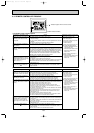
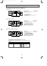
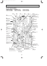
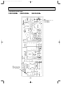
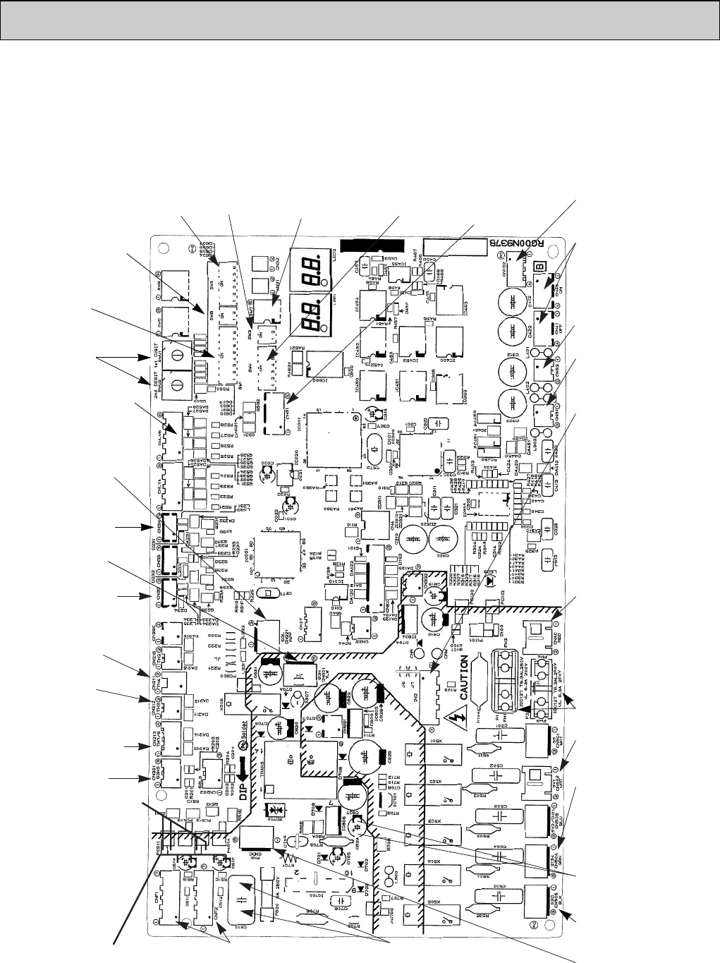
9-9. TEST POINT DIAGRAM
Outdoor multi controller board
PUMY-P100VHM PUMY-P125VHM PUMY-P140VHM
PUMY-P100VHMA PUMY-P125VHMA PUMY-P140VHMA
SW2
Pump down
21S4
4-way valve
SV1
Bypass valve
CNAC
Power supply for multi
controller board
CNS1
Indoor/ outdoor unit
connecting wire
CN52
Transmission wire of
centralized control
CN40,CN41
Centralized control power
supply/ For storing
jumper connector selection
CN102
Connect to the M-P.B
(Transmission power board)
CN51
External signal
output
SW4
Model select
SW7
Forced defrost
SW3
Test run
CN2
Connect to the outdoor
power circuit board
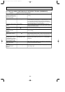
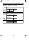
1-5:
Power circuit board ➔
Transmitting signal to
the multi controller board
(0-5V DC)
2-5: Zero cross signal
(0-5V DC)
3-4: Not used
6-5: 16V DC
7-5: 16V DC
CNDC
DC280V-350V
(1(+)–3(-))
VCC (TEST POINT2)
(Voltage between pins of
C82A) : DC15V
(Same as CNF1,2 5(+)–4(-))
VSP
(Voltage between pins of
C515 and C516) :
DC0V (when stopped)
DC1–6.5V (when operated)
(Same as CNF1,2 6(+)–4(-))
CNF1, 2
Connect to fan motors
1–4 : DC280V-350V
5–4 : DC15V
6–4 : DC0–6.5V
7–4 : DC15V (when stopped)
DC0–15V pulse
(when operated)
VDC (TEST POINT1)
(Voltage between pins of
C510) : DC280V-350V
(Same as CNF1,2 1(+)–4(-))
VFG
(Voltage between left pins of
PC511 and PC512, pin1
and pin2) :
(Same as CNF1,2 7(+)–4(-))
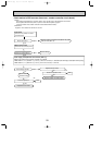
TH4 Thermistor
<Discharge>
TH7/ 6 Thermistor
<Outdoor/ Saturation temper-
ature of suction pressure>
63HS
High presser sensor
63H
High presser switch
TH3 Thermistor
<Outdoor pipe>
CN3D
Input of demand control
63L
Low pressure switch
SW1
Display selection
(Self diagnosis)
SWU2, SWU1
Address setting
SW8
Demand/ Silent selection
52C
52C relay signal
F1, F2
FUSE 6.3A
CN3N
Auto change over
(external signal input)
CNLVB(Only VHMA)
Connect to the outdoor
noise filter circuit board
(CN52C)1–6 : DC12V
OC376B--3.qxp 08.1.17 1:16 PM Page 61