35
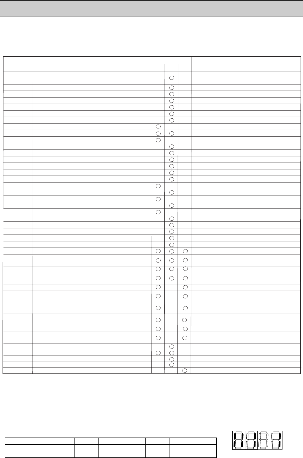
9-1-3. Countermeasures for Error During Test Run
• If a problem occurs during test run, a code number will appear in the temperature display area on the remote controller
(or LED on the outdoor unit), and the air conditioning system will automatically cease operating.
Determine the nature of the abnormality and apply corrective measures.
Check code
1102
1302
1500
1501
1505
2502
2500
2503
4115
4220
4230
4250
5101
5102
5103
5105
5106
5110
5201
6600
6602
6603
6606
6607
6608
6831
6832
6833
6834
7100
7101
7102
7105
7111
Piping temperature sensor trouble (TH3)
Outdoor temperature sensor trouble (TH7)
Heatsink temperature sensor trouble (TH8)
Pressure sensor trouble (63HS)
Current sensor trouble
Duplicated unit address setting
Transmission error
(Transmission processor hardware error)
Transmission error (Transmission route BUSY)
Transmission and reception error
(Communication trouble with transmission processor)
Transmission and reception error (No ACK error)
Transmission and reception error
(No responsive frame error)
MA communication receive signal error
(no receive signal)
MA communication send signal error
(starting bit derection error)
MA communication send error (H/W error)
MA communication receive error
(Synchronous recovery error)
Total capacity error
Capacity code error
Connecting unit number error
Address set error
Remote controller sensor trouble
Check delay code 1202
Check delay code 1402
Check delay code 1600
Check delay code 1601
Check delay code 4165
Check delay code 4320
Check delay code 4330
Check delay code 4350
Check delay code 1202
Check delay code 1211
Check delay code 1205
Check delay code 1221
Check delay code 1214
Check delay code 1402
Only M-NET Remote controller is detected.
Only M-NET Remote controller is detected.
Only M-NET Remote controller is detected.
Only M-NET Remote controller is detected.
Only M-NET Remote controller is detected. w
Only M-NET Remote controller is detected. w
Only MA Remote controller is detected.
Only MA Remote controller is detected.
Only MA Remote controller is detected.
Only MA Remote controller is detected.
0403
Serial transmission trouble
Discharge temperature trouble
Low Pressure trouble
High pressure trouble
Excessive refrigerant replenishment
Insufficient refrigerant trouble
Vacuum operation protection
Water leakage
Drain pump trouble
Drain sensor trouble (THd)
Overcurrent trouble (Overload, compressor lock)
Power synchronization signal trouble
Inverter trouble
Overheat protection of radiator panel
Power module trouble or Overcurrent trouble
Fan controller trouble (Outdoor)
Air inlet sensor trouble (TH21) or
Discharge temperature sensor trouble (TH4)
Liquid pipe temp.sensor trouble (TH22) or
Low pressure saturated temp.sensor trouble (TH6)
Gas pipe temperature sensor trouble (TH23)
Outdoor unit Multi controller board ~
Power board communication trouble
1300
Check delay code 1400
4100
Check delay code 4350
4400
Check delay code 4500
5300
Check delay code 4310
Trouble
Remarks
Detected unit
Indoor
Outdoor
Remote
controller
12345678
[Example]
When the compressor and
SV1 are turned during cooling
operation.
Bit
Indication
1
Compressor
operated
2
52C
3
21S4
4
SV1
5
(SV2)
6
—
7
—
8
Always lit
Self-diagnosis function
The indoor and outdoor units can be diagnosed automatically using the self-diagnosis switch
(SW1) and LED1, LED2 (LED indication) found on the multi-controller of the outdoor unit.
LED indication : Set all contacts of SW1 to OFF.
During normal operation
The LED indicates the drive state of the controller in the outdoor unit.
NOTE )
When the outdoor unit detects No ACK error/ No responsive frame error, an object indoor unit is treated
as a stop, and not assumed to be abnormal.
OC376B--2.qxp 08.1.17 1:15 PM Page 35


