


82
12 DISASSEMBLY PROCEDURE
OPERATING PROCEDURE
PHOTOS & ILLUSTRATION
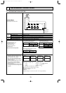
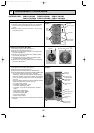
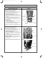
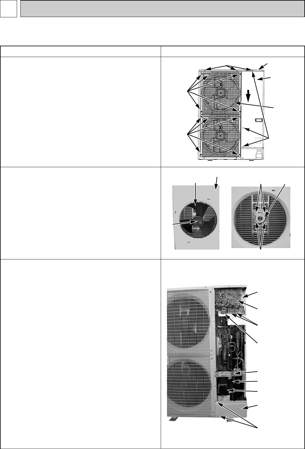
1. Removing the service panel and top panel
(1) Remove 3 service panel fixing screws (5 ✕ 10) and slide
the hook on the right downward to remove the service
panel.
(2) Remove screws (3 for front, 3 for rear/5 ✕ 10) of the top
panel and remove it.
Figure 1
Top panel fixing screws
Top panel
Service panel
fixing screws
Service panel
Grille
fixing
screws
Fan grille
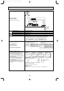
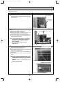
2. Removing the fan motor (MF1, MF2)
(1) Remove the service panel. (See figure 1.)
(2) Remove the top panel. (See figure 1.)
(3) Remove 5 fan grille fixing screws (5 ✕ 10) to detach the
fan grille. (See figure 1.)
(4) Remove a nut (for right handed screw of M6) to detach
the propeller. (See photo 1.)
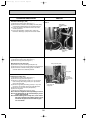
(5) Disconnect the connectors, CNF1 and CNF2 on Multi
controller board in electrical parts box.
(6) Remove 4 fan motor fixing screws (5 ✕ 25) to detach the
fan motor. (See photo 2.)
Fan motor fixing screws
Photo 3
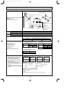
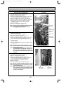
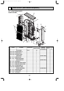
3. Removing the electrical parts box
(1) Remove the service panel. (See figure 1.)
(2) Remove the top panel. (See figure 1.)
(3) Disconnect the connecting wire from terminal block.
(4) Remove all the following connectors from Multi controller board;
fan motor, thermistor <Outdoor pipe>, thermistor
<Discharge>, thermistor <Low pressure saturated temp>,
thermistor <Outdoor>, high pressure switch, high pressure
sensor, low pressure switch, 4-way valve coil and bypass
valve coil.
Pull out the disconnected wire from the electrical parts box.
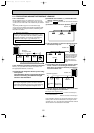
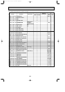
<Diagram symbol in the connector housing>
• Fan motor (CNF1, CNF2)
• Thermistor <Outdoor pipe> (TH3)
• Thermistor <Discharge> (TH4)
• Thermistor <Low pressure saturated temp, Outdoor>
(TH6/7)
• High pressure switch (63H)
• High pressure sensor (63HS)
• Low pressure switch (63L)
• 4-way valve coil (21S4)
• Bypass valve coil (SV1)
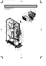
(5) Remove the terminal cover and disconnect the compressor
lead wire.
Photo 1
Fan
motor
Fan motor fixing screws
Propeller
Front panel
Nut
Photo 2
Grille
fixing
screws
Slide
Electrical
parts box
Terminal cover
Cover panel
(Front)
Cover panel
fixing screws
Valve bed
OUTDOOR UNIT : PUMY-P100VHM PUMY-P125VHM PUMY-P140VHM
PUMY-P100VHMA PUMY-P125VHMA PUMY-P140VHMA
Terminal block
(TB1)
Multi controller
board (MULTI.B)
Terminal block
(TB3) (TB7)
Continued to the next page.
Compressor (MC)
OC376B--3.qxp 08.1.17 1:16 PM Page 82