


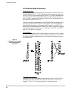

than 16 bits of data, this variable MUST be a short integer (%) array
variable. If you are reading registers or memory locations that are stored as
words and the # of registers/bits is greater than one, this will be a short
integer array (make sure you properly dimension the array prior to using it).
If you are reading the status of more than one, but less than 16 I/O bits, you
will be reading one word, and therefore will need to use a single short
integer. If you are reading more than 16 bits, you will need to use a short
integer array. The dimension of the array variable will be the next integer
greater than the desired number of bits divided by 16. For example, if you
wish to read the status of bits 1-24 you will need to dimension your array to
at least two since 24/16 = 1.5 and two is the next greater integer. Remember,
any time you are reading more than one word of data (more than one register
or more than 16 bits) you must use a dimensioned short integer array.
Examples:
10 DIM regdat%(10)
20 CALL PLCREAD(1,4,16,5,regdat%(4))
This command returns the contents of register 16 in regdat%(4), register 17
in regdat%(5), register 18 in regdat%(6), register 19 in regdat%(7), register 20
in regdat%(8), from any of the PLC’s currently implemented.
10 CALL PLCREAD(1,5,47,1,regdat1%)
This command reads the data in input register number 47 with id (address)
=1 and stores it in the variable regdat1%
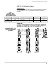
CALL PLCWRITE Statement
Purpose:
This command is used to write value(s) to the FX’s register(s), memory
location(s), or to force one or more output bits in a PLC.
Syntax:
CALL PLCWRITE(
id,cmd,start address,# of
registers/bits,expression/variable/array )
Comments:
id specifies the address of the FX - always use 1.
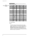
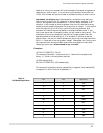
cmd specifies the write operation you wish to perform. See the table below
for the write operation possibilities:
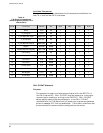
start address is the starting address of the bit(s) or register(s) you are
interested in writing. Inputs and Outputs (data types X and Y) are specified
in OCTAL just like you would specify in the PLC ladder logic program. The
type specified for this parameter if a variable is to be used is an integer: %.
# of registers/bits is the number of consecutive registers, memory locations,
or bits that you wish to write. If you wish to write one bit or register, set this
parameter to 1. If you wish to write more than one register or memory
T-60 Operator's Manual
96