


MRV Communications, Inc. – Installation Manual
3
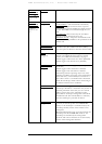
M (for Multimode)
S (for Single Mode)
‘Y’ represents operating wavelength.
Instead of Y use one of the following:
8 (for 850 nm)
3 (for 1310 nm)
5 (for 1550 nm)
‘Z’ represents connector type.
Instead of Z use one of the following:
C (for SC)
T (for ST)
‘V’ represents yes or not with Fusion.
Instead of V use one of the following:
V represents no built-in Fusion option.
F represents built-in Fusion option.
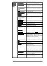
Power Supply
: Each product base code ends with * or **. * means that the
product has one power supply. **means that the product can have two power
supplies: one main and the other one - for back-up. In the products description,
there is a list of all compatible power supplies. When ordering, please specify the
required power supply and make sure that it is in the above list. For example, if a
TS5000/155 with one power supply, high voltage (100-240VAC) is required;
TS5000/XYZ/V1S should be ordered. Similarly, in case of 2 power supplies low
voltage (35-60VDC), the p/n will be TS5000/XYZ/V23. If the required product
can have only one power supply, for example TS5000/ETH, high voltage, the
p/n will be TS5000/ETH/VS.
‘S’ represents power supply type
Instead of S use one of the following:
S (for input to the power supply in the range 100-240 VAC)
3 (for input to the power supply in the range 35-60 VDC)
‘U’ represents telephony protocol type.
Instead of U use one of the following:
E (for E1)
T (for T1)
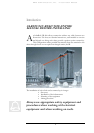
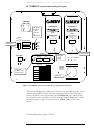
General Description
1. Front
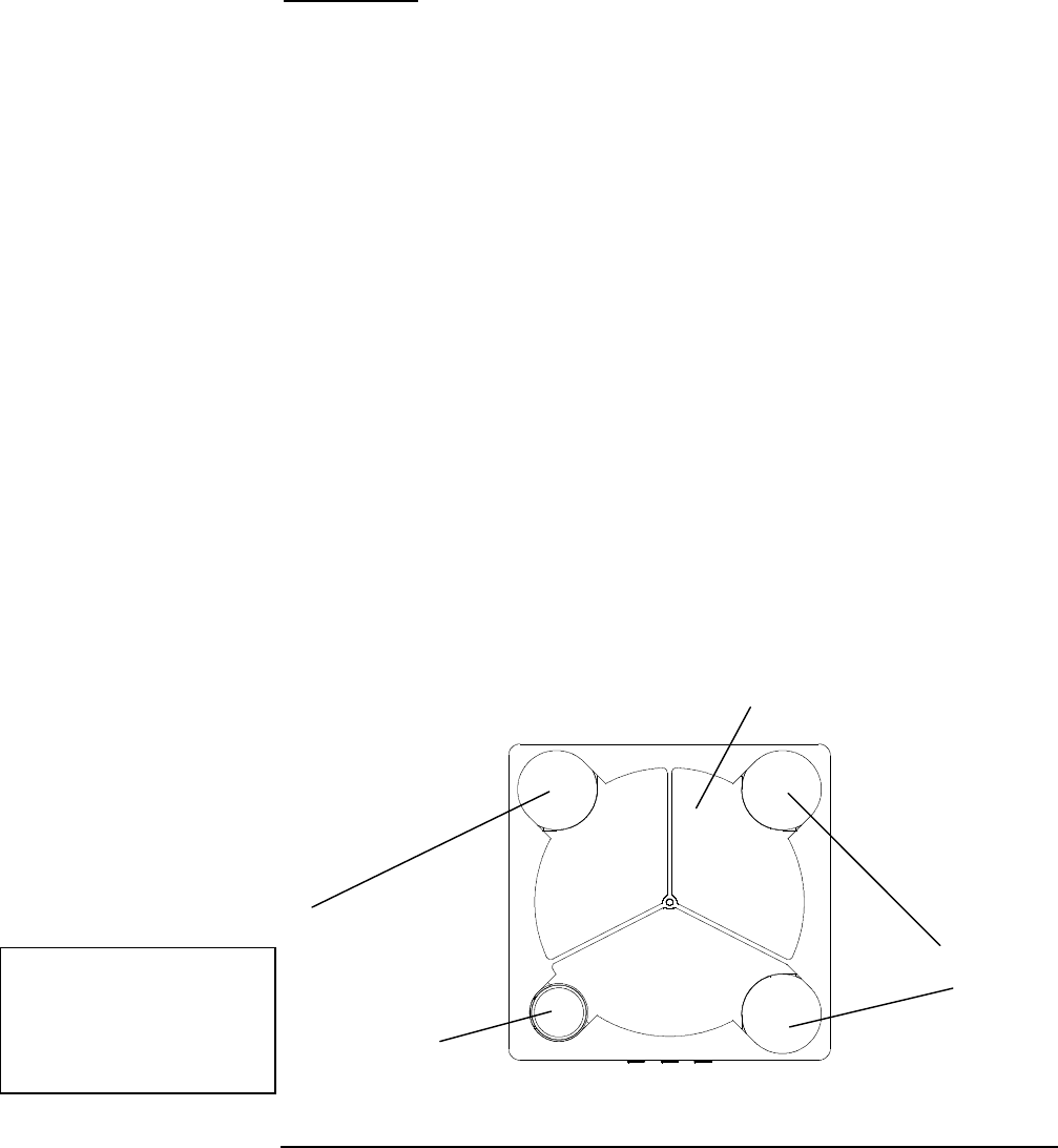
Each unit comprises a receiver, 3 transmitters and an interface on the rear panel for
the connection to the peripheral equipment.
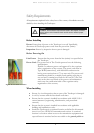
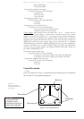
Figure 1.1: Front View Schematic
Front view
Showing the receiver
side, the transmitters and
the telescope
Telescope
Transmitter
Receiver
Transmitters
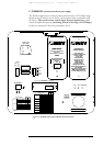
CAUTION!
AVOID EXPOSURE –
INVISIBLE LASER
RADIATION IS EMITTED
FROM THIS APERTURE