


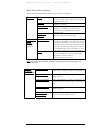
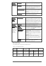
MRV Communications, Inc. – Installation Manual
26
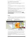
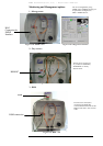
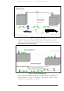
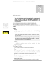
Figure 2.2: Acceptable Mounting
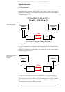
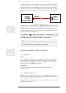
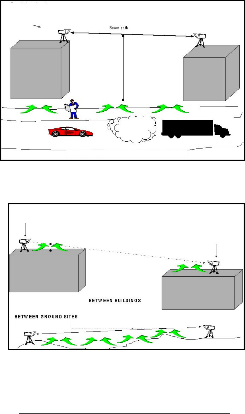
Figure 2.3 shows an unrecommended TereScope link location because of
interference by IR. Notice that the TereScopes are mounted far from the rooftop
edges or are too close to the ground.
Figure 2.3: Unrecommended Mounting
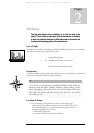
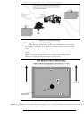
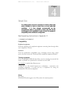
Figure 2.4 shows an unacceptable TereScope link location because of interference by
passing vehicles. Notice that the TereScopes are mounted far from the rooftop
edges and not high enough above the ground.
TereScope not at edge of roof.
TereScope not at edge of roof.
Beam path passes too close to ground. Heat rising causes scintillation.
Allow 4.5 m (15 ft) between ground and beam path.
Less than 4.5 m (15 ft) between beam
path and heat-emitting surface.
Beam path more than
4.5 m (15 ft) above
surface to avoid traffic
and rising heat.
TereScope at edge of roof so
that heat rising from roof
surface does not affect beam