


MRV Communications, Inc. – Installation Manual
14
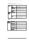
REMOTE MONITOR
OPTICAL POWER
SYNC
FLAG
AIR RX
LOOP
FUSION
HEATING
SW MODE
ALIGNMENT
MANAGEMENT
1766240
PS1 PS2 HEATER ON
Rx
3-6
Tx
1-2
Rx
Tx
TELESCOPE
L 3 ON
(BACK VIEW)
LASERS STATUS
L 2 ONL 1 ON
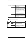
ON
OFF
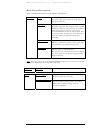
Normal
-
1,2
Local Loopback
Alignment
1 2
3
3
4
10
-
-
8
Mode Select
Remote Loopback
6
6
-
-
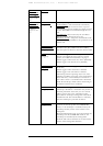
Laser Status
Fusion
Window Heater
(if exist)
IP Address Setup
Control Mode
Off
On
Laser Enable
Laser Disable
Disable
Enable
Off
On
Default IP
Software IP
HW MODE
SW MODE
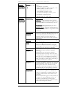
Alignment Signal
Attenuation
-
2
1,2
-
-
-
10
-
-
5
-
5
-
8
-
1
4
ON
OFF
-
1,2,3,4
2
2,3
4
2,4
1,2,3
2,3,4
1,3
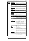
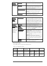
Data Rate
Fast Ethernet 100Mbps
ATM/OC3/STM1: 155Mbps
SMPTE: 143 Mbps
E3: 34.368 Mbps
T3: 44.736 Mbps
OC1/STM0: 51.840 Mbps
Customized 2
Open Protocol
1,2,4
1
3,4 1,2
3
1,4
4
1,3,4
1,2,3
Customized 1
USE COPPER CONDUCTORS ONLY
TORQUE VALUE 7 Lb-Inch
L
+/~
G
G
N
-/~
HIGH
V
OLT.
LOW VOLT.
POWER
POWER SUPPLY
USE COPPER CONDUCTORS ONLY
TORQUE VALUE 7 Lb-Inch
L
+/~
G
G
N
-/~
HIGH
V
OLT.
LOW VOLT.
POWER
POWER SUPPLY
FOR FUSION
MAIN
TX RX
TX RX
REDUNDANT
F I B E R O P T I C
FLAG FLAG
SYNC SYNC
1
10
1
10
DS 1 DS 2
TABLE FOR DS 2
TABLE FOR DS 1
AVOID EXPOSURE
INVISIBLE LASER RADIATION IS EMITTED FROM THIS APERTURE
DO NOT USE
TELESCOPE
TO LIFT UNIT ! !
CAUTION
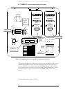
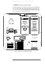
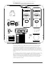
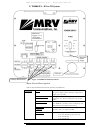
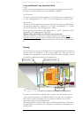
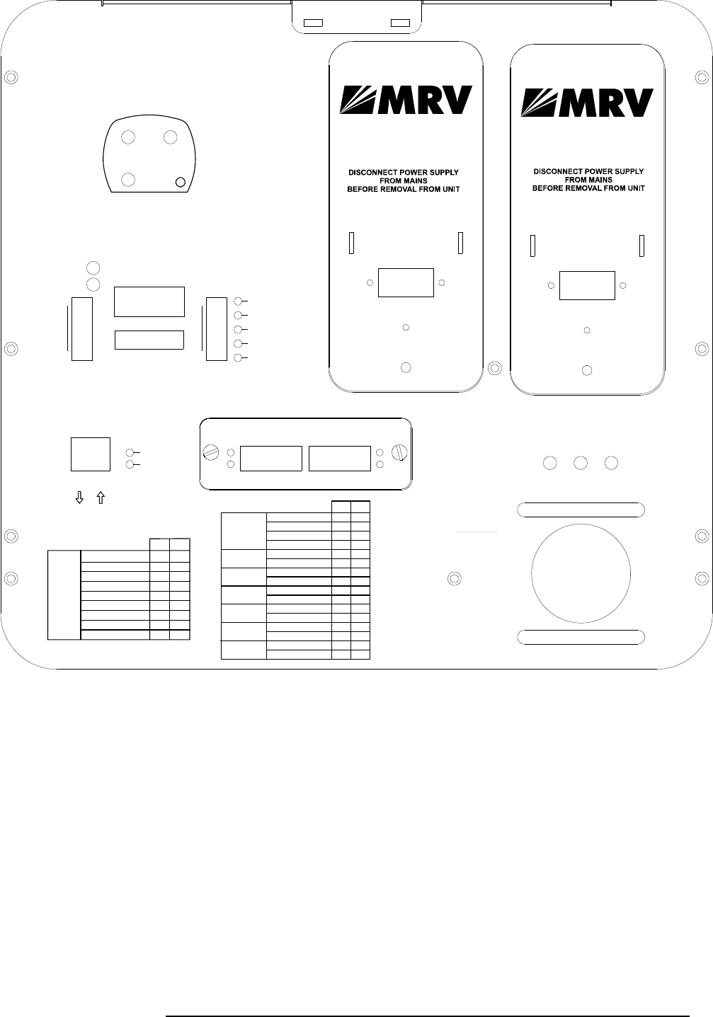
D. TS5000/155-F (Standard Model including Fusion option)
This special TS5000/155-F model can be connected to the back-up radio
system without special MRV’s Switch and card supporting Fusion. This
TereScope can be connected to any Switch (supporting 10/100) via standard
converter, which should be connected to the optical port of the TereScope
labeled “Redundant”, while the back-up radio system is connected to the same
Switch.
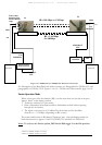
The TereScope can be also directly connected to MC (Media Converter) of the
type 10/100 TX-100 FX (for example MRV’s media converter MC102F).
When the TereScope stops operating, the connectivity from the main optical
module to the air channel stops and starts flowing into the second optical
module designated for radio.
Figure 1.6: TS5000/155-F
w
ith a redundant power supply Panel Schematic