


MRV Communications, Inc. – Installation Manual
48
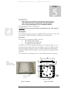
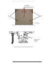
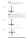
2. Fine
Alignment
E, J – opened.
L,D - closed
1) Open screws J-L-1,
J-L-2, and J-L-3 1 to
2 turns.
2) Tighten screws J-R-
1, J-R-2, and J-R-3 till
they are open for ¾
turns; i.e. slightly
tightened, but allow
for fine alignment.
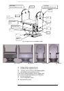
3) Do the alignment
with the help of the
alignment knobs B &
C
to place the opposite
Transceiver exactly in
the center of the target
of the telescope till
receipt of the signal on
RSSI meter.
4) Perform the fine
alignment procedure
given in the section
Fine Alignment on this
page (below).
3. Tightening
the Screws
1) Tighten screws E.
2) Tighten screws J-R-
2 and J-R-3 (2
screws).
3) Tighten screws J-L-
2, J-L-3, and J-L-1 (3
screws) in this order.
4. Finishing
the
Alignment
All screws are closed. To put down alignment
results – link distance;
-weather
condition;
-visibility;
-RSSI at both
sites.
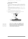
Fine Alignment
• This stage requires one person on each site.
• Provide yourself with a walkie-talkie, a mobile phone or any other
equipment giving you a way to talk to the assistant working on the
opposite site.
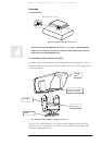
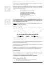
The target at this stage is to aim only the local transmitter, using the Fine Tuning
the 2 knobs B and C, so that the remote receiver will be positioned in the middle
of the beam cross section at the shot distance.
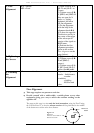
Figure 6.7:
Front view
Transceiver at the middle o
f
the beam cross section
V1
V2
H1
H2
TereScope
Beam Cross
Section