


MRV Communications, Inc. – Installation Manual
37
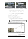
Display and Results
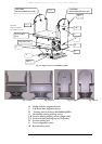
1. TS5000/G & TS5000/G-F
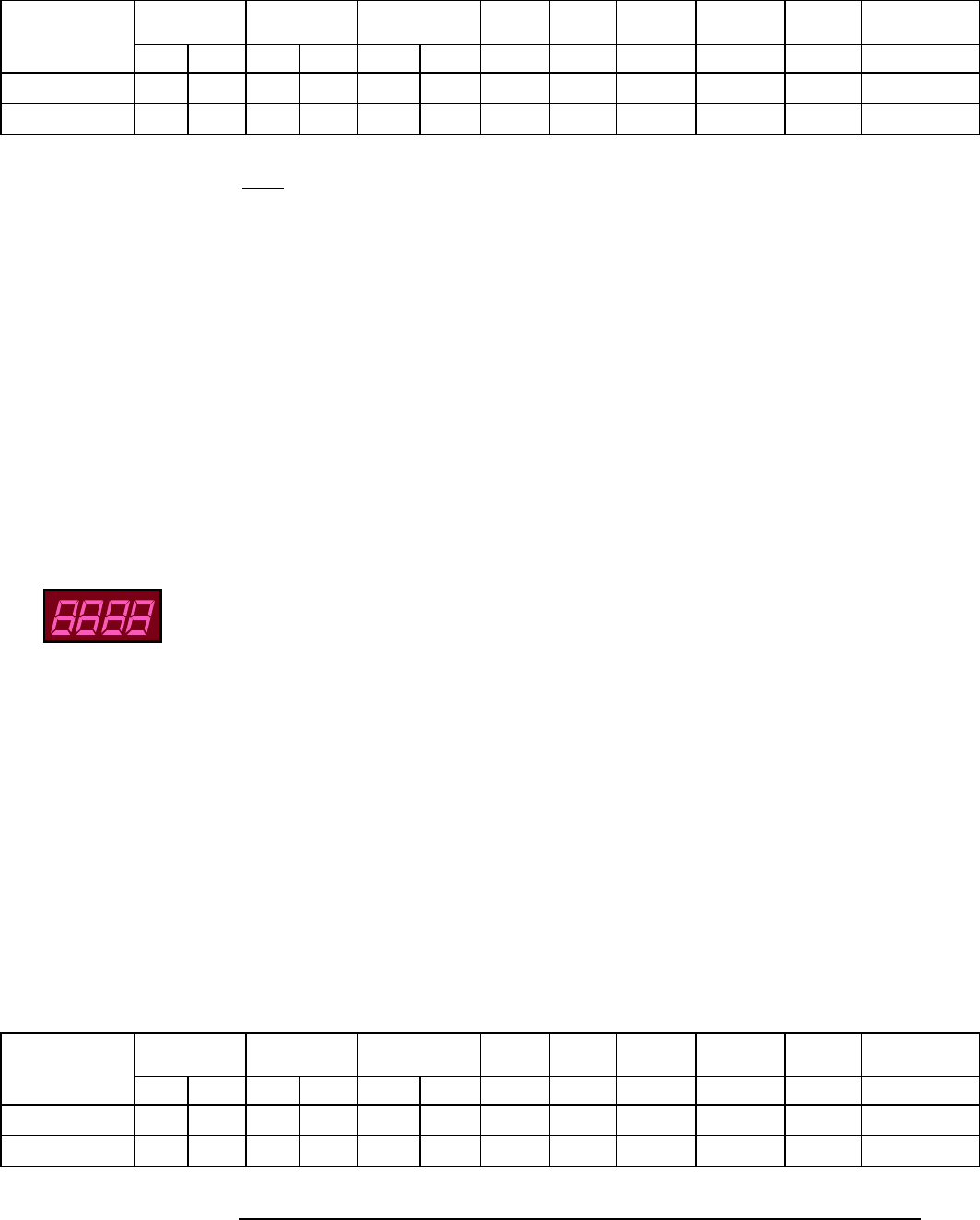
Proper Display
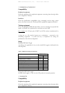
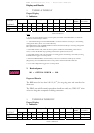
1. Indicators
Indicator →
AIR RX F/O RX
1
Management
2
Align. Loop Fusion
3
Heating
4
SW
Mode
5
Lasers Status
L1 to L3
6
Position ↓
Flag Sync TX RX TX RX
ON
x X
x
OFF
x x x x x x x x x
Notes
1 - In case the tested TereScope has a Fusion option, the LEDs of the redundant F/O should be
switched off if the backup is inactive.
2 – TX LED Flashing when the RSM-SNMP is connected and the TereScope is transmitting
management Data. (There is no Link indication)
RX LED Flashing when the RSM-SNMP is connected and the TereScope is receiving management
Data. (There is no Link indication)
3 - This LED switches ON, when the fusion option is enabled. It starts blinking, when fusion is
active, i.e. when the IR link stops operating and the back-up link becomes active.
4 - This LED switches ON only when there is a heating option. The heating is activated by moving
the DIP Switch toggle # 5 to ON position.
5 - When the RSM-SNMP is connected and you choose to control the TereScope by software
(Megavision), move the DIP Switch #10 to ON position and this LED will switch ON.
6 - L1 is OFF if Dip switch toggle #3 is on ON position
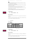
2. Received power
100 < OPTICAL POWER < 1000
Expected Results
The BER must be less than 10E-12 (10
-12
) for on-going tests and error-free for
short tests.
The PING test and file transfer procedure should not notify any TIME OUT alarm
or last too long time compared to cabling connection.
2.
TS5000/155 & TS5000/155-F
Proper Display
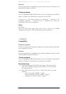
1. Indicators
Indicator →
AIR RX F/O RX
1
Management
2
Align. Loop Fusion
3
Heating
4
SW
Mode
5
Lasers Status
L1 to L3
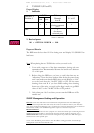
Position ↓
Flag Sync Flag Sync TX RX
ON
x x
x
x
x
OFF
x x x x x x x
T
able 8: Indicators
T
able 9: Indicators