


MRV Communications, Inc. – Installation Manual
28
3. Avoid surfaces with high reflectivity (e.g., white walls) behind the
TereScope so as to reduce interference with the optical signal.
4. Get customer approval for the exact positions where the TereScopes will
be mounted. Using paint, mark these positions.
5. Note the height that each TereScope will be above or aside the rooftop.
6. Identify the floor or wall type and dimensions of the location at which
the TereScope is planned to be mounted.
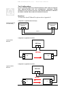
7. For each TereScope unit, select one of the following mounting options
2
and record it.
a. Parapet/Ledge Mounting (Figure 2.6) – This is a standard
mounting option that uses only the Plate (JMP).
b. Wall Mounting (Fig. 2.8) – This is a standard mounting option
that uses the Plate (JMP) as well as the two Brackets (JMB).
c. Floor Pedestal Mounting (Figure 2.7) – This is a non-standard
mounting option that uses the Plate (JMP) as well as a Floor Pedestal (e.g.,
M015C).
d. Wall Pedestal Mounting (Figure 2.9) – This is a non-standard
mounting option that uses the Plate (JMP) as well as a Wall Pedestal (e.g.,
M054C).
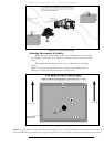
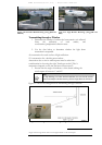
e. Extended Wall Mounting (Figure 2.10) – This is a non-
standard mounting option that uses the Plate (JMP) as well as an Extended
Wall (e.g., M062C).
f. Angle Bracket Mounting (Figure 2.11) – This is a non-
standard mounting option that uses the Plate (JMP) as well as an
Angle Bracket (e.g., M001).
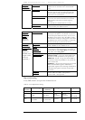
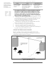
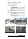
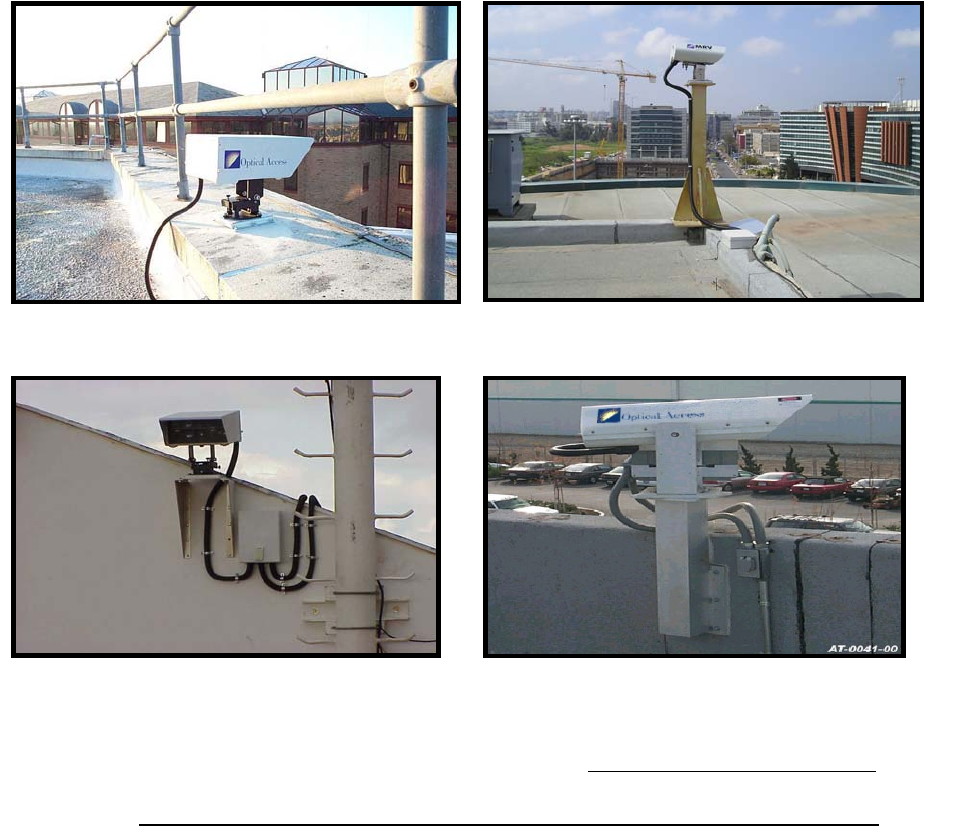
Figure 2.6: Parapet/Ledge Mounting (using JMP only)
Figure 2.7: Floor Pedestal Mounting (using JMP and
MO15C)
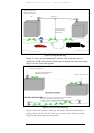
Figure 2.8: Wall Mounting (using JMP and JMB)
Figure 2.9: Wall Pedestal Mounting (using JMP and
MO54C)
2
For more information on these mounting options, refer to TereScope Installation Guide (Publication No.
46366).