


MRV Communications, Inc. – Installation Manual
31
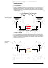
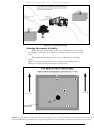
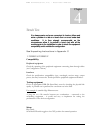
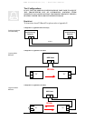
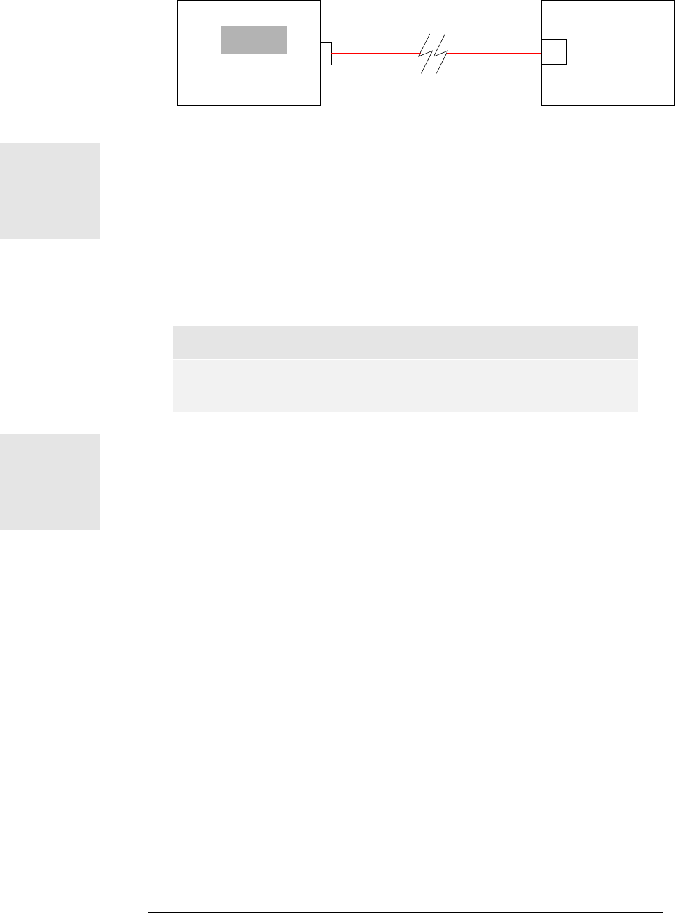
A simple power loss test can inform us about the condition of the fibers.
This test consists of measuring with an optical power meter the output
power at one end of the tested fiber as at the other end a fiber source is
connected. If the values are in dBm, the difference between the input
power and the output power gives the power attenuation of the fiber (in
dB).
Optical Power Meter
dBm
Peripheral
Equipment
or
Optical Source
F/O
TX
Fiber Optic
Cable
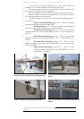
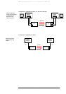
In case the above equipment is not available, a simple visual test may be
performed to locate and reject badly damaged fibers. Place near one end of
the fiber a light source and block alternatively the termination, you must
observe the light coming out of the other end. (This procedure does not
guarantee that a fiber is acceptable)
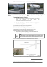
A standard 62.5μm fiber optic cable is characterised by an
attenuation factor of around 3 to 5dB/km. Then a loss value of more
than 3dB for runs up to 200m can indicate a suspect fiber.
Note
The fiber optic cables must be installed by a specialist.
HANDLE THE FIBERS VERY CAREFULLY.
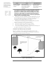
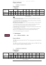
2. For TS5000/ETH
Type
For connecting the Transceiver to the peripheral equipment a 2 pairs STP
cable is required (one pair for the transmission and one for the reception).
This cable must be a straight one when the peripheral has an MDI-X 10
Base T interface and a Gross one otherwise.
Connectors
The cable should be terminated with an RJ-45 connector on the
Transceiver end.
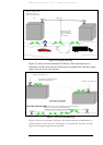
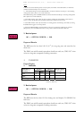
3. For TS5000/4U1 (4E1 or 4T1)
Type: For connecting the Transceiver to the peripheral equipment a 2
pairs STP cable is required (one pair for the transmission and the other for
the reception) for each E1 or T1 connection.
Connectors A special connector is provided by MRV to connect the
twisted pair cables to the TS.
Figure 3.1: F/O cable test.