


MRV Communications, Inc. – Installation Manual
19
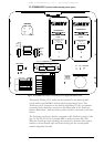
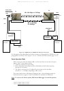
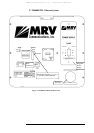
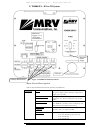
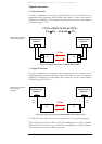
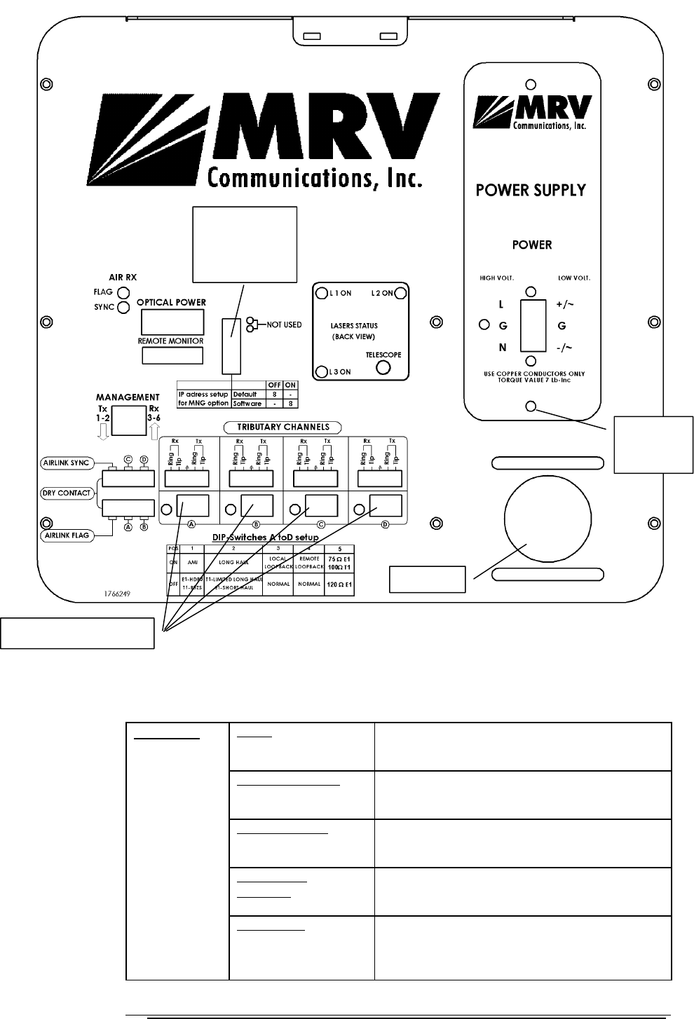
F. TS5000/4U1 - 4E1 or 4T1 System
Figure 1.9: TS5000-4U1 Model Back Panel
Back Panel Description
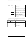
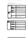
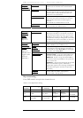
Table 5: 4E1/4T1 Back Panel Controls, Interfaces, and Indicators
Power Power source Terminal Block (Main or UPS).
AC power supply (100 to 240 Vac) or DC power
supply (35 to 60 Vdc)
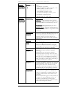
4 Data Connectors 4xCopper interface. Four green universal
connectors A to D to be used with coax or STP
cables.
Remote Monitor Connection to an optional Remote Status Monitor
or to RSM-DC (for Dry Contact connection) (not
included in the standard transceiver kit)
Management
(10baseT)
Connection to 10Base-T SNMP management
interface. Pins 1,2: TX and 3,6 RX.
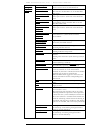
Connectors
Dry Contact 6 dry contact outputs:
1 for each interface port (total of 4)
1 for air-link flag
1 for air-link sync
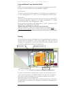
Pluggable
Power
Su
pp
l
y
Telesco
p
e
DIP Switch
Toggles 1-7, 9,
10 positions
are immaterial.
Tributary DIP Switches