


MRV Communications, Inc. – Installation Manual
46
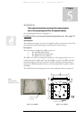
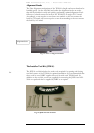
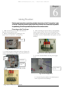
1 – Make sure that the power cable is disconnected
from the electrical power source.
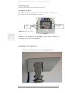
2 – Remove the Back Door by undoing the four
screws I (two on each side – see Figure 6.1.)
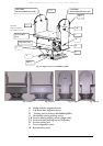
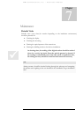
Fig. 6.2: Power cable Fiberoptic cable, and ‘N’
Screws
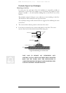
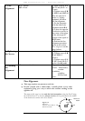
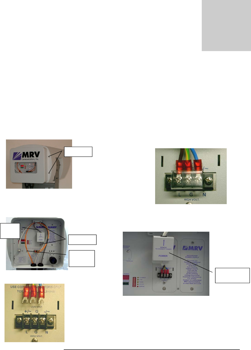
4 – After connecting the power cables to corresponding
sockets, tightly close the screws of the Terminal block –
see Figure 6.4. Gently jerk the cable to check that it stays
connected. Cover the Terminal Block with plastic cover (if
available).
Fig. 6.4: Power Terminal Block Locked
5 – Cover the Terminal Block with the power supply
cover.
6 – Connect the power cable to the electrical power
source to power on the TereScope.
Power
Cable
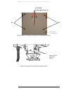
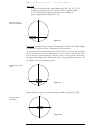
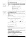
Aiming Procedure
Point to point connections require the orientation face to face of both “transceiving” ends
of the link. Concerning wireless optical links this should be done as accurate as possible
for positioning the beam symmetrically all around the remote receiver.
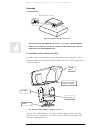
Powering on the TereScope
Chapter
6
Fiberoptic
Cable
Fi
g
. 6.1: Screws I
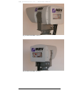
3 – Connect the wires of the power cable (see Figure 6.2)
to the Terminal Block (see Figure 6.3) paying attention to
L
=
Line, G
=
Ground & N
=
Neutral.
Fig. 6.3: Power cable & Terminal block
Fi
g
. 6.5: Power Su
pp
l
y
Cover
Power Supply
Cover
'I' Screws
'N' Screws