


ION 7500 / ION 7600 User’s Guide Analog Inputs
Chapter 5 - Features and Applications Page 145
Analog Inputs
Analog inputs can measure and store analog information such as electrical signals
from transducers; transducers derive the electrical signals from flow rates,
temperatures, pressures, rotations, and fluid levels. They are controlled by Analog
Input modules.
Analog inputs require the installation of an optional circuit board inside the meter.
The I/O card provides four analog inputs. By default, four Analog Input modules
(labeled
AI1 to AI4) are already created for this purpose. Configure the settings of
the controlling module to match your requirements. The settings in these modules
are as follows:
1
An arbitrary input value can be treated as the Zero Scale (i.e., a 4-20mA input is capable of generating
a 0 to X output).
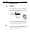
Analog Outputs
An ION meter’s analog outputs act as transducers. The meter measures power and
energy, and then sends that information via the analog outputs to a remote
terminal unit (RTU). The analog outputs issue industry standard 0 to 20 mA
current signals. They are controlled by the Analog Output modules.
Analog inputs require the installation of an optional circuit board inside the meter.
The I/O Card provides four analog outputs. By default, four Analog Output
modules (labeled
AO1 to AO4) are already created for this purpose. Configure the
settings of the controlling module to match your requirements. The settings in
these modules are as follows:
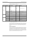
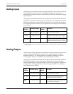
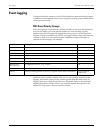
Setup
Registers
Available Settings
Creation
Default
Description
Port
Not Used or
AI1 to AI4 inclusive
Not Used The input hardware channel
Full Scale
-1 x 10
9
to 1 x 10
9
1
Defines what value appears in the
ScaledValu output register when the highest
possible value from the hardware is applied
Zero Scale
1
-1 x 10
9
to 1 x 10
9
0
Defines what value appears in the
ScaledValu output register when the lowest
possible value from the hardware is applied
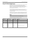
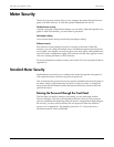
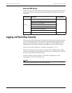
Setup
Registers
Available Settings
Creation
Default
Description
Port
Not Used
AO1 to AO4 inclusive
Not Used The output hardware channel
Full Scale
-1 x 10
9
to 1 x 10
9
1
Defines what value appears in the ScaledValu
output register when the highest possible
value from the hardware is applied
Zero
Scale
-1 x 10
9
to 1 x 10
9
0
Defines what value appears in the ScaledValu
output register when the lowest possible value
from the hardware is applied