


®
TECHNICAL NOTE
Current Probe Inputs Basic Setup
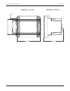
Meters with the Current Probes Input Option are compatible with clamp-on current
probes. All current inputs on these meters are modified to accept 0-5 Vrms AC
signals from a variety of clamp-on current probes. This option reduces the downtime
required to install a meter. There are two Current Probe Input Option
configurations:
A. Meters calibrated and shipped with probes: the meter is pre-configured and
calibrated at the factory with three Universal Technic 10A current probes,
meeting IEC 1036 Class 1 accuracy levels which includes the meter and the
current probes accuracy. The current probes can be used for monitoring 1A or
5A secondaries. Probe cable is 22 AWG (0.3 mm
2
) and two meters in length.
B. Meters calibrated, but not with probes: this option allows you to order a meter
that is calibrated for use with current probes. You then supply your own probes
(as long as they match the input specifications of the meter) or select one of the
several compatible models available from PML as accessories. Probes and probe
cables must be compliant with IEC 61010-1 CATIII protection requirements and
not require more than 220k Ohm of load impedance.
Whether basic setup is necessary depends on your Current Probe Input Option.
Basic Setup is NOT required:
If your ordering option includes PML supplied current probes and a meter factory-
calibrated to match the current probe specifications (option “A” above).
If you have this ordering option, then this document does not apply to you.
Basic Setup IS required:
If your meter ordering option does not include current probes that have been
factory-calibrated with the meter (option “B” above). In this case, you need to set
up the transformation ratio for the current probes you will be using. If energy
readings accuracy is important, then you need to set up the phase angle specified
by the current probe manufacturer. To learn how to do this setup, read the
following instructions.
In This Document
◆ Telnet and HyperTerminal Access . . . . . . . . . . . . . . . . . . . . . . . . . . . . . . . 186
◆ Current Probe Basic Setup . . . . . . . . . . . . . . . . . . . . . . . . . . . . . . . . . . . . 186
To perform current probe basic setup: . . . . . . . . . . . . . . . . . . . . . . . . . . . . . . 187
◆ Calibration Menu and the KCTSTP/KCTRD Commands . . . . . . . . . . . . . . . 188
Calibration Menu and Help . . . . . . . . . . . . . . . . . . . . . . . . . . . . . . . . . . . . . . . . . . . 188
Description of KCTSTP and KCTRD Calibration Commands . . . . . . . . . . . . . . 188