


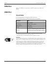
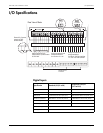

ION 7500 / ION 7600 User’s Guide COM1 Port
Chapter 6 - Hardware Reference Page 165
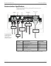
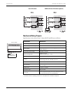
External Modem Connections
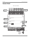
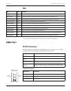
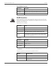
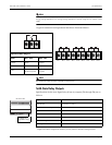
RS-485 Connections
RS-485 connections are made via the captured-wire connectors on the rear of the meter.
Devices can be connected in series using RS-485 (see diagram to the left). Be sure not to
ground the wires at both ends.
Specifications are as follows:
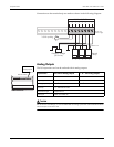
Connections
1
The lengths of all (+ and –) cable segments must be counted including those that connect devices to
terminal blocks.
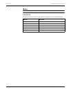
Terminal connections on the meter are marked as follows:
Specification Description
Cable Type Standard straight-through RS-232 cable
Cable Ends DB9 female end for mating with the DB9 male connector on the meter
Max. Cable Length 50 feet (15.2 m)
Specification Value
Baud Rates 300 to 57,600 bps (default is 9,600 bps)
Duplex Half
Supported Protocols
ION, Modbus RTU, DNP 3.0, FACTORY, Iec870-102, GPS: Arbiter,
GPS: TRUE TIME DATUM, EtherGate, ModemGate (default is ION)
Isolation
Optical isolation from all other inputs and outputs (the COM1 RS-485 port
is not isolated from the COM1 RS-232 port); isolation voltage is 750 V
peak for 10 seconds @ 60 Hz.
Specification Description
Cable Type Good quality shielded twisted pair cable, AWG 22 or larger.
Max. Cable Length
4,000 ft. (1219 m)
1
Max. number of
devices per bus
32
Marking Terminal Function
SHLD RS-485 Shield
– RS-485 Data Minus
+ RS-485 Data Plus
SH
+
-
SH
COM
RS-485
+
-