


I/O Expansion Card ION 7500 / ION 7600 User’s Guide
Page 178 Chapter 6 - Hardware Reference
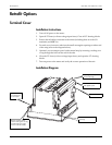
Final Steps
4. Ensure the cover meets the chassis of the base unit.
5. Use the Phillips screwdriver to replace the two backplate screws, as well as the
nut on the chassis ground lug, with their lock-washers. They must be installed
firmly to preserve transient immunity.
6. Reinstall the Line and Neutral (or DC power) wiring to the Control Power inputs
of the unit.
7. Reconnect all other wiring (or re-enable all other circuits). Close the PT fuses (or
direct voltage input fuses), and open the CT shorting blocks.
8. Turn on power to the meter and verify the correct operation of the unit.
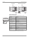
I/O Expansion Card
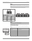
The standard I/O expansion card has 8 digital (status) inputs labelled DI1 to DI8.
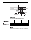
Depending on what you ordered, the I/O expansion card will also contain either 4
analog inputs, or 4 analog outputs, or both. Check the label on the I/O Card for
your I/O specifications.
Installation Instructions
The following steps should be taken before inserting an I/O Card into the meter:
1. Turn off all power to the meter.
2. Open all PT fuses (or direct voltage input fuses). Close all CT shorting blocks.
3. Disconnect the Line and Neutral (or DC power) wires from the Control Power
inputs of the unit.
4. Disconnect all other wiring (or power off all other circuits) which may present
potentially hazardous voltage levels to the unit, such as connections to the relay
outputs, status inputs, etc.
5. Ensure that all cables still connected to the meter are NOT live.
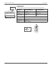
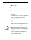
Installing the I/O Card
The I/O Card consists of a circuit board with an attached polarized CHAMP
connector on the component side. Follow these steps to install the I/O Card:
1. If present, remove the plastic tab that seals the I/O Card’s cover plate to the
meter. Use the Phillips screwdriver to remove the plate’s two screws, then
remove the plate.
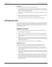
2. Hold the I/O card by the sides and slide it into the base unit with the component
side facing up. Slide the edge of the circuit board down the slots along each side
of the chassis.
3. Align the CHAMP connector with the socket and press the I/O Card firmly into
place. The socket and the connector are polarized, so the pins in the connector
will not fit into the socket if the card is not oriented correctly. The I/O card is
securely inserted into the socket when the backplate of the I/O Card meets the
chassis of the meter.