


9-64 Upgrading Your Server
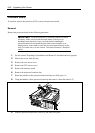
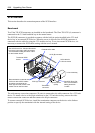
SCSI Interface
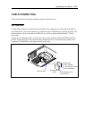
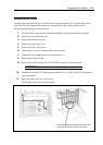
This section describes the connection pattern of the SCSI interface.
Baseboard
Two Ultra 320 SCSI connectors are installed on the baseboard. The Ultra 320 SCSI (A) connector is
connected to the 3.5-inch hard disk bay in the normal status.
The SCSI (B) connector is provided to connect with the built-in option installed in the 5.25-inch
device bay or an external SCSI device. When the server is delivered, the SCSI (B) connector is
connected with the cable for using the 5.25-inch device bay. To use an external SCSI device, it is
necessary to connect the SCSI cable coming with the server instead.
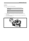
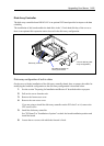
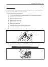
The wide-narrow conversion connector (50 pins) is connected to the cable connector for a 5.25-inch
device. To install a device with 68-pin connector on the 5.25-inch device bay, remove the wide-
narrow conversion connector and then connect the 68-pin connector.
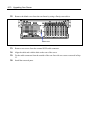
To connect external SCSI devices, install the termination connector on the device at the furthest
position or specify the termination with the internal setting of the device.
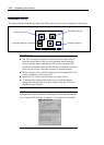
External SCSI cable
SCSI (B) connector
SCSI cable for
5.25-inch device
3.5-inch disk bay
Set SCSI IDs to ID0 -
ID6. The termination
setting should be
"invalid."
Optional device
(SCSI)
Termination
connecto
r
SCSI (A) connector
To external SCSI
device.
Set SCSI IDs to ID0 - ID6 (the IDs should
be unique in the daisy chain connection).
The termination setting should be "valid"
for the furthest device.
Because both the external and
5.25-inch device SCSI cables
should be connected to the
SCSI (B) connector, either of the
cables can be used at a time.