


2-28 General Description
POST Flow
The flow of operations executed by POST is sequentially described below:
IMPORTANT: Depending on the system configuration, message
"Press Any Key" requesting key entry may appear on the display screen.
This is requested by BIOS on an installed optional board. See the
explanation described in the manual for the option and press any key.
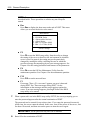
1. After power-on, POST is activated to start the memory check. The message indicating the
counted size of the base memory and that of the additional memory appears at the upper
left corner of the display screen. In addition, the following message appears at the bottom
of the screen.
Press <ESC> to enter boot selection menu, <Space> to abort memory test
Press <F2> to enter SETUP, <F4> Service Partition, <F12> Network
NOTE: Pressing Space under the display of message "<Space> to
abort memory test" allows the memory test to be skipped.
It may take several minutes to complete the memory check depending on the size of the
memory installed in the server. Similarly, it may take about a minute to display the proper
information on the screen at rebooting.
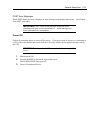
2. Detects the SCSI controller built in the server and displays the message prompting the
start of the SCSI BIOS setup utility (without any key entry for several seconds, POST is
automatically continued). Press the proper keys according to the screen display.
Press <Ctrl> <A> for SCSISelect(TM) utility!
Now press Ctrl + A to start the utility. See Chapter 4 for the setting procedures and
features of the parameters.
For example, the SCSI BIOS setup utility must be used in the following cases:
Installation of an SCSI device in the 5.25-inch device bay
Connection of an external SCSI device (The removal of the SCSI cable for 5.25-inch
device in the server and the connection of the SCSI cable coming with the server (for
external connection) are required.)
Modification of SCSI device connections within the server
If the SCSI BIOS setup utility is terminated, the server runs POST from its start again.
When more than one SCSI controller boards are installed on the PCI bus of the server, the
messages indicating the starts of the SCSI BIOS setup utilities for the installed boards
appear in the following order:
PCI slot number PCI #1, PCI #2, PCI #3, PCI #4, PCI #5, PCI #6, PCI #7, and PCI #8.