


General Description 2-5
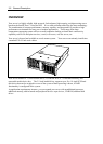
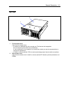
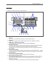
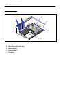
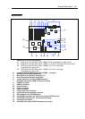
Front View (with Front Bezel Removed)
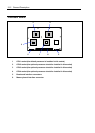
See Chapter 8 for detail information on lamp indication.
1 Power supply unit
The power supply unit supplies DC powers to the server. The slot 1-3 is for optional slot.
2 Power lamp
When the power of the server is turned on, the lamp goes on green.
3 AC Standby lamp
If the power cord is connected to the AC inlet to supply AC power to the power supply unit, the
lamp goes on green except for the lamp indicated AC_R. If the power system of the server is in
the redundant function, after turning on the server, the lamp indicated AC_R goes on green.
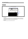
4 5.25-inch device bay
Backup tape drives may be installed in the 5.25-inch device bay.
5 CD-ROM drive
The CD-ROM drive reads data from the inserted CD-ROM.
5-1: Access lamp (lit orange during accessing)
5-2: CD tray eject button
5-3: Emergency hole
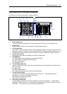
6 3.5-inch floppy disk drive
Insert a 3.5-inch floppy disk to the 3.5-inch floppy disk drive to read data from the disk or write
data to the disk.
6-1: Eject button
6-2: Disk inserting section
6-3: Floppy disk access lamp (lit green during accessing)
7 3.5-inch hard disk bay
The 3.5-inch hard disk bay contains additional hard disk slots. Hard disks having the
thickness of 1 inch can be inserted into the slots.
The SCSI IDs are defined as follows:
ID0 to ID4 from right to left
8 Disk lamp (green/amber)
The disk lamp is lit green if a hard disk installed in the server is accessed. If a hard disk is
defected, the lamp is lit amber. During the rebuild processing, the lamp is lit green or amber
alternately. (This occurs only in the disk array configuration.)
1-1
2
1-2 1-3
5-1
5-2
5-3
3 4 7
8
6-1 6-2 6-3