


CHAPTER 3 ND-46550 (E)
Page 20
Revision 2.0
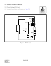
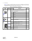
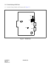
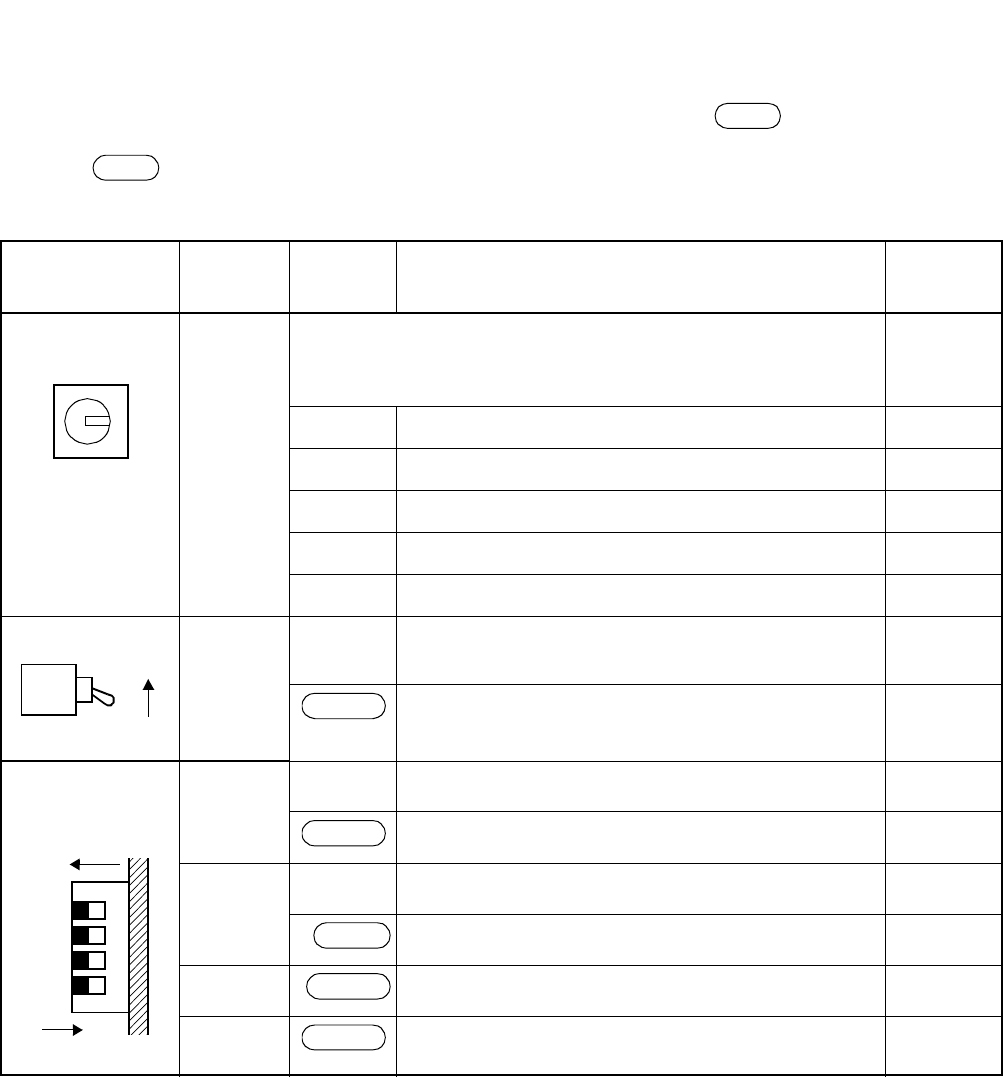
(3) Switch Settings
In Table 3-2, the figure in the SWITCH NAME column and the position in in the SETTING POSI-
TION column indicate the standard setting of the switch. When the switch is not set as shown by the figure
and , the setting of the switch varies with the system concerned.
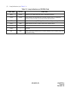
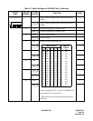
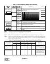
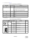
Table 3-2 Switch Settings on PN-DAIA Card
SWITCH
NAME
SWITCH
NUMBER
SETTING
POSITION
FUNCTION CHECK
SW1 (Rotary
SW)
Note 1
Note 2
0 – F FP (Firmware Processor) Number setting for DAIA card.
By this setting, system regards DAIA card and the opposite DAIB
card as one firmware processor.
0 Not used
1 FP No. 1
2 FP No. 2
3 FP No. 3
4 – F Not used
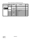
MB (Toggle SW)
Note 3
UP For make-busy
For normal operation
SW1 (Piano Key
SW)
1
Note 4
ON For supplying 1.5 MHz clock to PLO 0
No clock supply to PLO 0
2
Note 4
ON For supplying 1.5 MHz clock to PLO 1
No clock supply to PLO 1
3
Always set to OFF
4
Always set to OFF
1
3
2
ON
OFF
ON
OFF
4
3
2
1
OFF
OFF
OFF
OFF