


ND-46550 (E) CHAPTER 3
Page 27
Revision 2.0
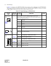
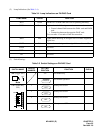
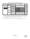
In Table 3-5, the figure in the SWITCH NAME column and the position in in the SETTING
POSITION column indicate the standard setting of the switch. When the switch is not set as shown by the
figure and , the setting of the switch varies with the system concerned.
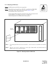
Note: When the power is on, flip the MB switch to ON (UP position) before plugging/unplugging the circuit card.
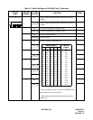
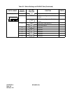
SW3 (Dip SW) 1 Set the equalizer according to the cable
length between the system and the CSU.
OFF
2
OFF
3
OFF
4 ON When mounting this card on remote
site.
OFF When mounting this card on main site.
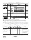
Table 3-5 Switch Settings on PN-DAIC Card (Continued)
SWITCH NAME
SWITCH
NUMBER
SETTING
POSITION
FUNCTION CHECK
ON
2134
ON
SW-1 SW-2 SW-3 CABLE LENGTH
ON ON ON 0 - 131.2 ft (0 - 40 m)
ON ON OFF 131.2 - 262.5 ft. (40 - 80 m)
ON OFF ON 262.5 - 394 ft. (80 - 120 m)
ON OFF OFF 394 - 525 ft. (120 - 160 m)
OFF ON ON 525 - 656 ft. (160 - 200 m)
OFF OFF OFF Signal is not sent
ON
ON