


ND-46550 (E) LIST OF FIGURES
Page iii
Revision 2.0
LIST OF FIGURES
Figure Title Page
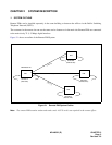
2-1 Remote PIM System Outline .............................................................................................................. 3
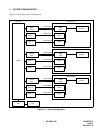
2-2 System Configuration ......................................................................................................................... 5
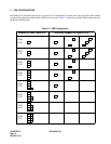
2-3 Time Slot Allocation............................................................................................................................ 10
2-4 Time Slot Allocation (Continued) ........................................................................................................ 11
3-1 Static Electricity Guard ....................................................................................................................... 13
3-2 Static-Sensitive Attention Symbol....................................................................................................... 14
3-3 Installation Procedure for Main Site.................................................................................................... 16
3-4 Installation Procedure for Remote Site............................................................................................... 17
3-5 PN-DAIA Card .................................................................................................................................... 18
3-6 Mounting Location of DAIA Card ........................................................................................................ 23
3-7 PN-DAIC Card .................................................................................................................................... 24
3-8 Mounting Location of DAIC Card (Main Site)...................................................................................... 28
3-9 BUS-DAIA Cable Connection ............................................................................................................. 29
3-10 DAIA-DAIC Cable Connection............................................................................................................ 30
3-11 DAIA-DAIC Cable Connection (Continued) ........................................................................................ 31
3-12 DAIA-DAIC Cable Connection (Continued) ........................................................................................ 32
3-13 DAIA-DAIC Cable Connection (Continued) ........................................................................................ 33
3-14 PN-DAIB Card .................................................................................................................................... 34
3-15 Mounting Location of DAIB Card ........................................................................................................ 39
3-16 Mounting Location of DAIB Card (Continued) .................................................................................... 40
3-17 Mounting Location of DAIC Card (Remote PIM).................................................................................41
3-18 Mounting Location of DAIC Card (Remote PIM) (Continued)............................................................. 42
3-19 Mounting Location of DAIC Card (Remote PIM) (Continued)............................................................. 43
3-20 DAIB-DAIC Cable Connection............................................................................................................ 44
3-21 Mounting Location of Line/Trunk Card (Small Platform)..................................................................... 45
3-22 Location of Each LEN (Small Platform) .............................................................................................. 46
3-23 LTC Connector Pin Arrangement (Small Platform)............................................................................. 47
3-24 Mounting Location of Line/Trunk Card (1000 IVS) .............................................................................48
3-25 Location of Each LEN (1000 IVS)....................................................................................................... 49
3-26 LTC Connector Pin Arrangement (1000 IVS) ..................................................................................... 50
3-27 Mounting Location of Line/Trunk Card................................................................................................ 51
3-28 Location of Each LEN (PIM N_UB)..................................................................................................... 52
3-29 LTC Connector Pin Arrangement (PIM B - UB) ..................................................................................53
3-30 PFT Connection Outline (PN-AUCA).................................................................................................. 54
3-31 MDF Cross Connection for PFT (PN-AUCA)......................................................................................55
3-32 PFT (PZ-8PFTA) Connection Outline ................................................................................................. 56