


ND-46550 (E) CHAPTER 3
Page 23
Revision 2.0
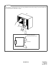
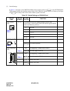
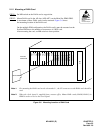
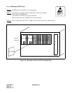
2.1.2 Mounting of DAIA Card
STEP 1:
Set MB switch on the DAIA card to up position.
STEP 2: Mount DAIA card in the AP slots (AP0-AP7) on the Main Site PIM0-PIM5.
A maximum of three DAIA cards can be mounted. Figure 3-6 shows
the mounting location of the DAIA card.
On the multiple PIM configuration, the DAIA card(s) must be mounted on the
first/last PIM due to the number of connectors of a BUS card.
After mounting the card, set MB switch to down position.
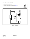
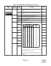
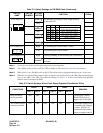
Figure 3-6 Mounting Location of DAIA Card
ATTENTION
Contents
Static Sensitive
Handling
Precautions Required
Main Site
PIM0-PIM5
PWR
LT09
LT01
LT02
LT03
LT04
LT05
LT06
LT07
LT08
LT00
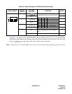
Note 1: For mounting the DAIA card on the slot marked , the CN connector on the DAIA card should be
used.
Note 2: When the clock signal is supplied from a master office, Mount DAIA cards (DAIA0, DAIA1) in
PIM0 in order to receive the clock signal.
*
*
DAIA CARD
LT10/AP0
LT11/AP1
LT12/AP2
LT13/AP3
LT14/AP4
LT14/AP5
LT15/AP6
MP/FP/AP7
BUS/AP8