


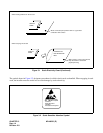

CHAPTER 3 ND-46550 (E)
Page 22
Revision 2.0
Note 1:
Set the groove on the switch knob to the desired switch position.
Note 2: Since DAIA card acts like an FP, the SW1 for DAIA in FPs cannot be set to the same number.
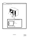
Note 3: When power is on, flip MB switch to ON (UP position) before plugging/unplugging the circuit card.
Note 4: When the clock signal from a master office is supplied via the line between the Main Site and the Remote
Site, set the SW1-1 and SW1-2 according to settings in Table 3-3. In this case, DAIA cards (DAIA0,
DAIA1) must be mounted in PIM0.
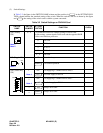
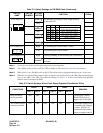
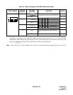
SW3 (Dip SW) 1 Set equalizer according to cable length between
system and CSU.
OFF
2
OFF
3
OFF
4 Always set to OFF
JPS (Jumper pin) Right For mounting this card on PIM1 ~ PIM7
Left For mounting this card on PIM0
JPR (Jumper pin) Right Neutral grounding on the receiving line is provided.
Neutral grounding on the receiving line is not
provided.
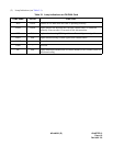
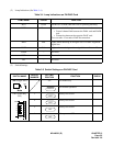
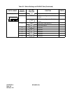
Table 3-3 Switch Settings When Clock Signal Supplied From Master Office
CONDITIONS
DAIA0 DAIA1 DAIA2
REMARKS
SW1-1 SW1-2 SW1-1 SW1-2 SW1-1 SW1-2
Only one DAIA
card is provided.
ON OFF - - - - Clock signal is sent to
PLO0 of MP card via
supply route 0 (DAIA0).
Two or three DAIA
cards are provided.
ON OFF OFF ON OFF OFF Clock signal supply route
is automatically changed
to route 1 (DAIA1) if
transmission line failure
occurs on supply route 0.
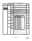
Table 3-2 Switch Settings on PN-DAIA Card (Continued)
SWITCH
NAME
SWITCH
NUMBER
SETTING
POSITION
FUNCTION CHECK
ON
2134
ON
SW-1 SW-2 SW-3 CABLE LENGTH
ON ON ON 0 - 131.2 ft. (0 - 40 m)
ON ON OFF 131.2 - 262.5 ft. (40 - 80 m)
ON OFF ON 262.5 - 394 ft. (80 - 120 m)
ON OFF OFF 394 - 525 ft. (120 - 160 m)
OFF ON ON 525 - 656 ft. (160 - 200 m)
OFF OFF OFF Signal is not sent
ON
ON
OFF
Left