


YML856 Rev3 NCT480 IP DSLAM User GuideNCT480 IP DSLAM User Guide
www.netcomm.com.au 13
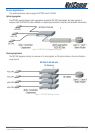
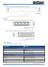
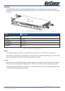
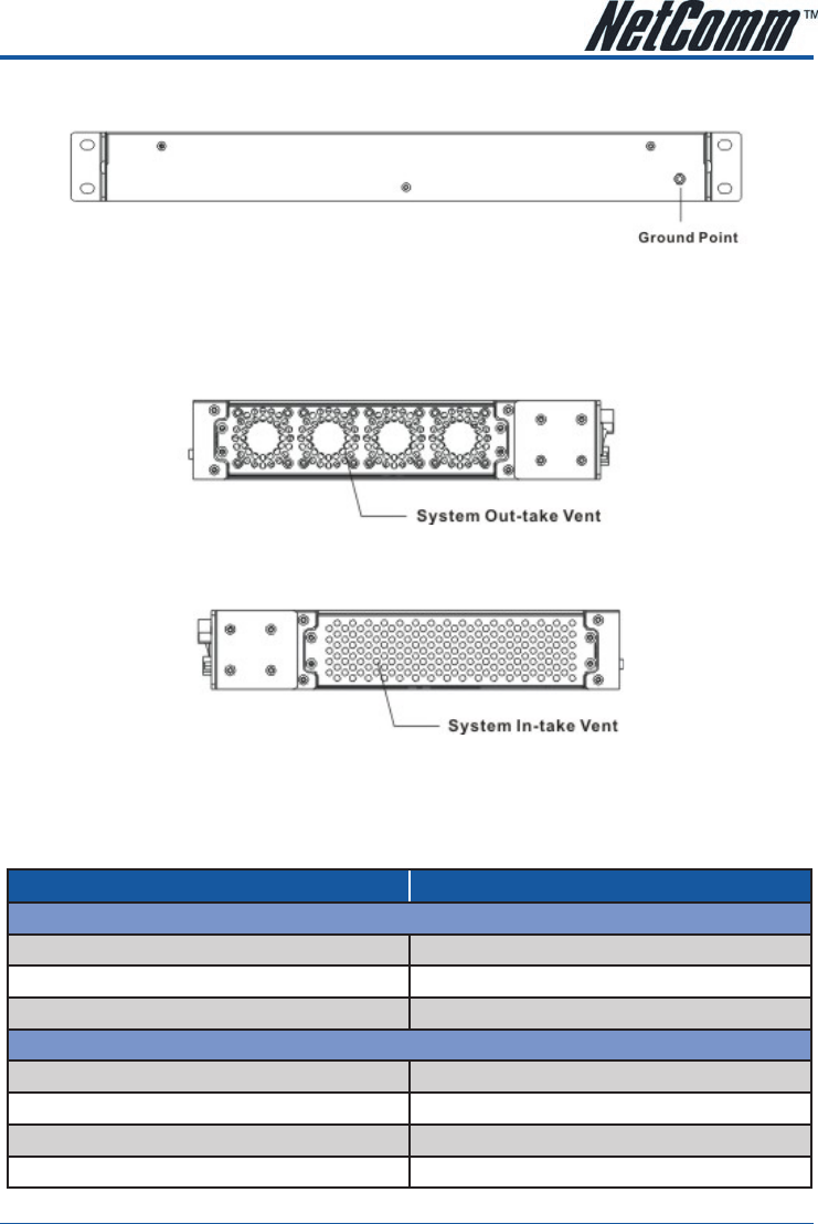
Rear View
The Figure 2-7 shows the rear panel of the NCT480 mini IP-DSLAM.
Figure 2-7 NCT480 Rear View
The equipment has provision for a permanently connected Protective Earthing Conductor.
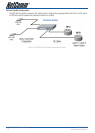
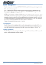
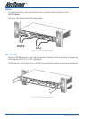
Side View
The Figure 2-8 shows the Left-hand Side view of the NCT480 mini IP-DSLAM.
Figure 2-8 Left-hand Side View
The Figure 2-9 shows the Right-hand Side view of the NCT480 mini IP-DSLAM.
Figure 2-9 Right-hand Side View
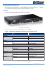
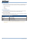
Alarm I/O Module
The Alarm I/O Module contains alarm I/O relay.
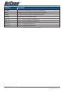
Digital I/O Pin Description
Output Pin (for alarm output receptacle)
CO
Common pin
NO
Circuit with normal open pin
NC
Circuit with normal close pin
Input Pin (for alarm input relay)
1 (+), 2 (-)
First pair of input signal terminal
3 (+), 4 (-)
Second pair of input signal terminal
5 (+), 6 (-)
Third pair of input signal terminal
7 (+), 8 (-)
Fourth pair of input signal terminal
Table 2-3 NCT480 Alarm I/O Relay Pin Description for Hardware revision 7 face panel