


NCT480 IP DSLAM User Guide YML856 Rev3
94 www.netcomm.com.au
APPENDIX B SYSTEM CONNECTOR PIN-OUTS
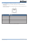
NCT480 System connector Pin-outs contains RJ-21 Subscriber connector, RJ-45 to RS-232 DB-9 adapter
local craft management, and RJ-45 GE Network uplink and Management interface.
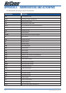
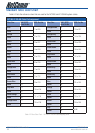
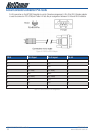
RJ-21 xDSL Connector Port Mapping
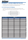
The female RJ-21 (Champ) subscriber connectors are located at the rear of NCT480 box chassis.
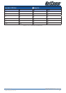
Table A-1 shows ADSL and POTS connectors correspond to ports on ADSL – J1/J2, Line – J1/J2, and
POTS J1/J2.
Figure A-1 RJ-21 Connector
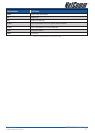
Line Port / POTS Port Champ Pin
J1 J2 Tip Ring
1 25 1 26
2 26 2 27
3 27 3 28
4 28 4 29
5 29 5 30
6 30 6 31
7 31 7 32
8 32 8 33
9 33 9 34
10 34 10 35
11 35 11 36
12 36 12 37
13 37 13 38
14 38 14 39
15 39 15 40
16 40 16 41
17 41 17 42
18 42 18 43
19 43 19 44