


NCT480 IP DSLAM User Guide YML856 Rev3
28 www.netcomm.com.au
Attach and Apply Power
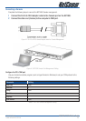
Complete the instruction to connect the DC power cord to NCT480.
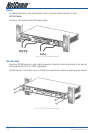
Figure 4-7 Front Panel AC Power Connection for NCT480
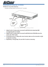
1 Ensure the power switch is set to the off position.
2 Use the Philip-head screwdriver to turn the screws on the terminal block
counterclockwise to losses the terminal connectors, GND (positive), -48VDC (negative),
and ground.
3 Remove the PVC wrapping of the wire to be connected to the terminal block
4 Insert the end of the wire into the corresponded receptacle with the terminal block
behind the screws. They must be fully inserted into the terminal block, so that no bare
wire is exposed.
5 Tighten the screws and pull on the wire to verify that it is held firmly in place.
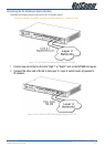
6 If you are connecting a second power source, repeat Step 2 to Step 5 for the
second block.
7 Turn on the power switch and visually check that the Power LED at front panel is On.
The input voltage tolerance limits for DC power are -36 to -60 VDC.