


Making the Physical Connections 3-3
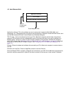
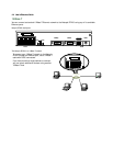
3. Connect the Ethernet cable to any of the Ethernet ports on the router.
(If you are connecting the router to an existing Ethernet hub, use Ethernet port #1 on the router and set the
crossover switch to the Uplink position.)
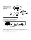
You should now have: the power adapter plugged in; the Ethernet cable connected between the router and
your computer; and the SDSL cable connected between the router and the SDSL wall outlet.
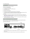
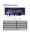
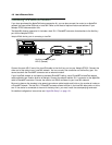
Netopia R7200 SDSL Router back panel ports
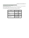
The following table describes all the Netopia R7200 SDSL Router back panel ports.
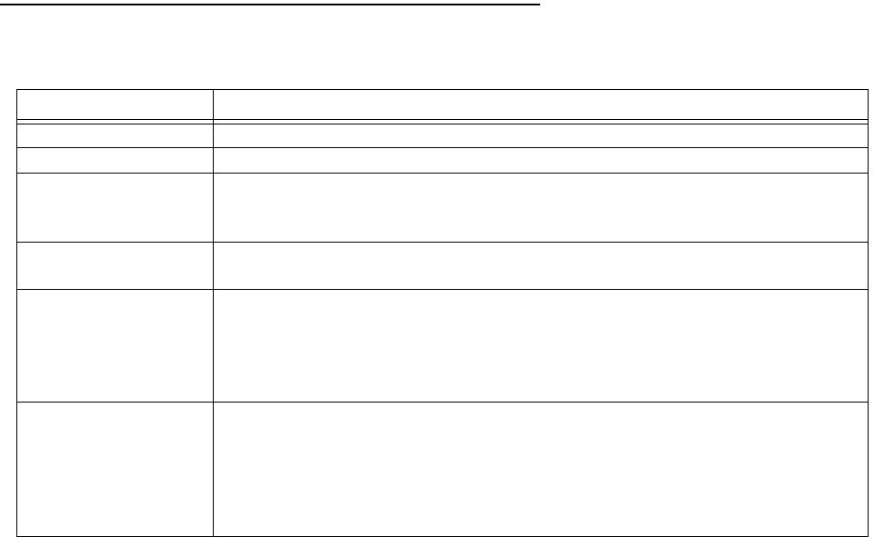
Port Description
Power port A mini-DIN8 power adapter cable connection.
Line port An RJ-11 telephone-style jack labeled Line for your SDSL connection.
Console port A DE-9 console port for a direct serial connection to the console screens. You
can use this if you are an experienced user. See “Connecting a console cable to
your router” on page 6-3.
Auxiliary port An HD-15 auxiliary port for attaching an external modem or the optional
AppleTalk kit.
Crossover switch A crossover switch with Normal and Uplink positions. If you use Ethernet Port
#1 for a direct Ethernet connection between a computer and the router, set the
switch to the Normal position. If you are connecting the router to an Ethernet
hub, use Ethernet port #1 on the router and set the switch to the Uplink
position.
8-port Ethernet hub Eight Ethernet jacks. You will use one of these to configure the Netopia R7200.
For a new installation, use the Ethernet connection. Alternatively, you can use
the console connection to run console-based management using a direct serial
connection. You can either connect your computer directly to any of the Ethernet
ports on the router, or connect both your computer and the router to an existing
Ethernet hub on your LAN.