


Alteon OS Application Guide
110
Chapter 5: Spanning Tree Group 42C4911, January 2007
Multiple Spanning Trees
Each GbE Switch Module supports a maximum of 128 Spanning Tree Groups (STGs). Multi-
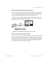
ple STGs provide multiple data paths, which can be used for load-balancing and redundancy.
You enable load balancing between two GbE Switch Modules using multiple STGs by config-
uring each path with a different VLAN and then assigning each VLAN to a separate STG. Each
STG is independent. Each STG sends its own Bridge Protocol Data Units (BPDUs), and each
STG must be independently configured.
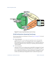
The STG, or bridge group, forms a loop-free topology that includes one or more virtual LANs
(VLANs). The switch supports 128 STGs running simultaneously. The default STG 1 may
contain an unlimited number of VLANs. All other STGs 2-128 may contain only one VLAN
each.
Default Spanning Tree configuration
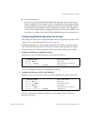
In the default configuration, a single STG with the ID of 1 includes all non-management ports
on the switch. It is called the default STG. Although ports can be added to or deleted from the
default STG, the default STG (STG 1) itself cannot be deleted from the system.
All other STGs, except the default STG 1 and the management STG 127 and STG 128, are
empty and VLANs must be added by the user. However, you cannot assign ports directly to
an STG. Add ports to a VLAN and add the VLAN to the STG. The default configuration of
management STG 127 contains VLAN 4094 and port EXT7. The default configuration of
management STG 128 contains VLAN 4095 and internal management ports MGT1 and
MGT2.
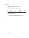
Each STG is enabled by default, and assigned an ID number from 2 to 126. By default, the
spanning tree on the management ports (MGT1, MGT2, and EXT7) is turned off in both STP/
PVST+ mode and in MSTP/RSTP mode.