


Alteon OS Application Guide
Chapter 5: Spanning Tree Group
11142C4911, January 2007
Why Do We Need Multiple Spanning Trees?
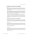
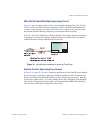
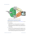
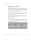
Figure 5-1 shows a simple example of why we need multiple Spanning Trees. Two VLANs,
VLAN 1 and VLAN 100 exist between application switch A and GbE Switch Module B. If
you have a single Spanning Tree Group, the switches see an apparent loop, and one VLAN
may become blocked, affecting connectivity, even though no actual loop exists.
If VLAN 1 and VLAN 100 belong to different Spanning Tree Groups, then the two instances
of Spanning Tree separate the topology without forming a loop. Both VLANs can forward
packets between the switches without losing connectivity.
Figure 5-1 Using Multiple Instances of Spanning Tree Group
Switch-Centric Spanning Tree Group
In Figure 5-2 on page 112, VLAN 2 is shared by application switch A and GbE Switch Module
B on ports 8 and 17 respectively. Application Switch A identifies VLAN 2 in Spanning Tree
Group 2 and GbE Switch Module B identifies VLAN 2 in Spanning Tree Group 1. Spanning
Tree Group is switch-centric—it is used to identify the VLANs participating in the Spanning
Tree Groups. The Spanning Tree Group ID is not transmitted in the BPDU. Each Spanning
Tree decision is based on the configuration of that switch.
BladeCenter
GbE Switch
Module B
GbE Switch
Module B