


Alteon OS Application Guide
Chapter 13: High Availability
23942C4911, January 2007
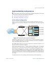
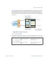
Figure 13-8 illustrates a common hot-standby implementation on a single blade server. Notice
that the BladeCenter server NICs are configured into a team that shares the same IP address
across both NICs. Because only one link can be active at a time, the hot-standby feature con-
trols the NIC failover by having the Standby switch disable its internal ports (holding down the
server links).
Figure 13-8 Hot-Standby Configuration
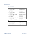
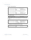
Task 1: Configure GbESM 1
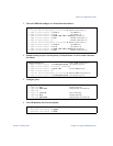
1. On GbESM 1, configure the interfaces for clients (174.14.20.110) and servers (10.1.1.110).
/cfg/l3/if 1
>> IP Interface 1# addr 174.14.20.110 (Define IP address for interface 1)
>> IP Interface 1# ena (Enable interface 1)
>> IP Interface 1# ..
>> Layer 3# if 2
>> IP Interface 2# addr 10.1.1.110 (Define IP address for interface 2)
>> IP Interface 2# ena (Enable interface 2)
Internet
Internet
Enterprise
Routing Switch
Server 2
Active
GbESM 1
Hot Standby
GbESM 2
NIC 1 IP = 10.0.1.1
Server 1
NIC 1 IP = 10.0.1.2
IF 1: 174.14.20.110
IF 2: 10.1.1.110
VIR 1: 174.14.20.100
VIR 2: 10.1.1.100
IF 1: 174.14.20.111
IF 2: 10.1.1.111
VIR 1: 174.14.20.100
VIR 2: 10.1.1.100
= Active Links
= Standby Links