


Alteon OS Application Guide
Chapter 5: Spanning Tree Group
11342C4911, January 2007
VLAN 3 Participation
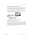
For VLAN 3 you can have GbE Switch Module B or application switch C to be the root
bridge. If switch B is the root bridge for VLAN 3, Spanning Tree Group 2, then switch B
transmits the BPDU out from port 18. Application switch C receives this BPDU on port 8
and is identified as participating in VLAN 3, Spanning Tree Group 2. Since application
switch C has no additional ports participating in Spanning Tree Group 2, this BPDU is not
forwarded to any additional ports and GbE Switch Module B remains the designated root.
Configuring Multiple Spanning Tree Groups
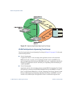
This configuration shows how to configure the three instances of Spanning Tree Groups on the
switches A, B, C, and D illustrated in Figure 5-2 on page 112.
By default Spanning Trees 2-126 are empty, and Spanning Tree Group 1 contains all config-
ured VLANs until individual VLANs are explicitly assigned to other Spanning Tree Groups.
You can have only one VLAN per Spanning Tree Group except for Spanning Tree Group 1.
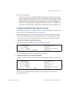
1. Configure the following on application switch A:
Add port 8 to VLAN 2 and define Spanning Tree Group 2 for VLAN 2.
VLAN 2 is automatically removed from Spanning Tree Group 1.
2. Configure the following on GbE Switch Module B:
Add port 17 to VLAN 2, port 18 to VLAN 3 and define Spanning Tree Group 2 for VLAN 3.
VLAN 3 is removed from Spanning Tree Group 1 and, by default, VLAN 2 remains in
Spanning Tree Group 1.
>> # /cfg/l2/vlan2 (Select VLAN 2 menu)
>> VLAN 2# add 8 (Add port 8)
>> VLAN 2# ../stg 2 (Select Spanning Tree Group 2)
>> Spanning Tree Group 2# add 2 (Add VLAN 2)
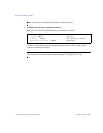
>> # /cfg/l2/vlan2 (Select VLAN 2 menu)
>> VLAN 2# add 17 (Add port 17)
>> VLAN 2# ../vlan3 (Select VLAN 3 menu)
>> VLAN 3# add 18 (Add port 18)
>> VLAN 3# ../stg 2 (Select Spanning Tree Group 2)
>> Spanning Tree Group 2# add 3 (Add VLAN 3)