


Alteon OS Application Guide
Chapter 13: High Availability
22142C4911, January 2007
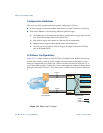
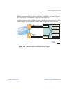
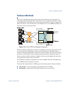
Figure 13-2 shows a configuration with two trunks, each in a different Failover Trigger.
GbESM 1 is the primary switch for Server 1 and Server 2. GbESM 2 is the primary switch for
Server 3 and Server 4. VLAN Monitor is turned on. STP is turned off.
If all links go down in trigger 1, GbESM 1 disables all internal ports that reside in VLAN 1. If
all links in trigger 2 go down, GbESM 1 disables all internal ports that reside in VLAN 2.
Figure 13-2 Two trunks, each in a different Failover Trigger
Internet
Internet
Enterprise
Routing Switch
GbESM 1
GbESM 2
Trigger 2
Trigger 1
Trigger 1
Trigger 2
BladeCenter
VLAN 1:
VLAN 2:
VLAN Monitor = O
nOn
Server 1
Server 3
Server 2
Server 4