


Alteon OS Application Guide
210
Chapter 12: OSPF 42C4911, January 2007
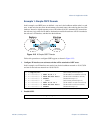
6. Define the stub area.
7. Attach the network interface to the backbone.
8. Attach the network interface to the transit area.
9. Configure the virtual link.
The nbr router ID configured in this step must be the same as the router ID that was config-
ured for switch #1 in Step 2 on page 207.
10. Apply and save the configuration changes.
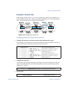
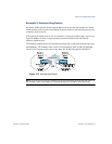
Other Virtual Link Options
You can use redundant paths by configuring multiple virtual links.
Only the endpoints of the virtual link are configured. The virtual link path may traverse
multiple routers in an area as long as there is a routable path between the endpoints.
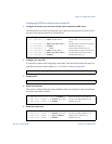
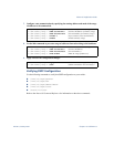
>> OSPF Area (index) 1 # ../aindex 2 (Select the menu for area index 2)
>> OSPF Area (index) 2 # areaid 0.0.0.2 (Set the area ID for OSPF area 2)
>> OSPF Area (index) 2 # type stub (Define area as stub type)
>> OSPF Area (index) 2 # enable (Enable the area)
>> OSPF Area (index) 2 # ../if 1 (Select OSPF menu for IP interface 1)
>> OSPF Interface 1 # aindex 1 (Attach network to transit area index)
>> OSPF Interface 1 # enable (Enable the transit area interface)
>> OSPF Interface 1 # ../if 2 (Select OSPF menu for IP interface 2)
>> OSPF Interface 2 # aindex 2 (Attach network to stub area index)
>> OSPF Interface 2 # enable (Enable the stub area interface)
>> OSPF Interface 2 # ../virt 1
(Specify a virtual link number)
>> OSPF Virtual Link 1 # aindex 1
(Specify the transit area for the virtual link)
>> OSPF Virtual Link 1 # nbr 10.10.10.1
(Specify the router ID of the recipient)
>> OSPF Virtual Link 1 # enable
(Enable the virtual link)
>> OSPF Interface 2 # apply
(Global command to apply all changes)
>> OSPF Interface 2 # save
(Global command to save all changes)