


Alteon OS Application Guide
198
Chapter 12: OSPF 42C4911, January 2007
The OSPF default route configuration can be removed with the command:
Virtual Links
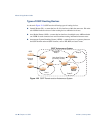
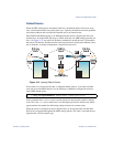
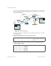
Usually, all areas in an OSPF AS are physically connected to the backbone. In some cases
where this is not possible, you can use a virtual link. Virtual links are created to connect one
area to the backbone through another non-backbone area (see Figure 12-1 on page 189).
The area which contains a virtual link must be a transit area and have full routing information.
Virtual links cannot be configured inside a stub area or NSSA. The area type must be defined
as transit using the following command:
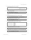
The virtual link must be configured on the routing devices at each endpoint of the virtual link,
though they may traverse multiple routing devices. To configure a GbE Switch Module as one
endpoint of a virtual link, use the following command:
where <link number> is a value between 1 and 3, <area index> is the OSPF area index of the
transit area, and <router ID> is the IP address of the virtual neighbor (nbr), the routing device
at the target endpoint. Another router ID is needed when configuring a virtual link in the other
direction. To provide the GbE Switch Module with a router ID, see the following section
Router ID.
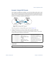
For a detailed configuration example on Virtual Links, see “Example 2: Virtual Links” on page
207.
>> # /cfg/l3/ospf/default none
>> # /cfg/l3/ospf/aindex <area index>/type transit
>> # /cfg/l3/ospf/virt <link number>/aindex <area index>/nbr <router
ID>