


Alteon OS Application Guide
Chapter 13: High Availability
23342C4911, January 2007
High Availability Configurations
GbE Switch Modules offer flexibility in implementing redundant configurations. This section
discusses the more useful and easily deployed configurations:
“Active-Active Configuration” on page 233
“Hot-Standby Configuration” on page 238
Active-Active Configuration
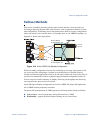
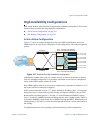
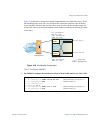
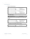
Figure 13-7 shows an example configuration where two GbE Switch Modules are used as
VRRP routers in an active-active configuration. In this configuration, both switches respond to
packets.
Figure 13-7 Active-Active High-Availability Configuration
Although this example shows only two switches, there is no limit on the number of switches
used in a redundant configuration. It is possible to implement an active-active configuration
across all the VRRP-capable switches in a LAN.
Each VRRP-capable switch in an active-active configuration is autonomous. Switches in a vir-
tual router need not be identically configured.
In the scenario illustrated in Figure 13-7, traffic destined for IP address 10.0.1.1 is forwarded
through the Layer 2 switch at the top of the drawing, and ingresses GbESM 1 on port EXT1.
Return traffic uses default gateway 1 (192.168.1.1). If the link between GbESM 1 and the
Layer 2 switch fails, GbESM 2 becomes the Master because it has a higher priority. Traffic is
forwarded to GbESM 2, which forwards it to GbESM 1 through port EXT5. Return traffic uses
default gateway 2 (192.168.2.1), and is forwarded through the Layer 2 switch at the bottom of
the drawing.
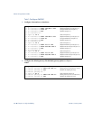
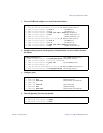
To implement the active-active example, perform the following switch configuration.
Internet
Internet
Enterprise
Routing Switch
GbESM 1
GbESM 2
Server 1
VIR 1: 192.168.1.200 (Master)
VIR 2: 192.168.2.200 (Backup)
VIR 1: 192.168.1.200 (Backup)
VIR 2: 192.168.2.200 (Master)
NIC 1: 10.0.1.1/24
NIC 2: 10.0.2.1/24
NIC 1: 10.0.1.2/24
NIC 2: 10.0.2.2/24
NIC 1: 10.0.1.3/24
NIC 2: 10.0.2.3/24
NIC 1: 10.0.1.4/24
NIC 2: 10.0.2.4/24
Server 2
Server 3
Server 4
L2 Switch
L2 Switch
1
2
5
5
1
2