


Alteon OS Application Guide
Chapter 12: OSPF
20942C4911, January 2007
Configuring OSPF for a Virtual Link on Switch #2
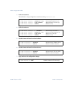
1. Configure IP interfaces on each network that will be attached to OSPF areas.
Two IP interfaces are needed on Switch #2: one for the transit area network on 10.10.12.0/24
and one for the stub area network on 10.10.24.0/24.
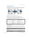
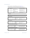
2. Configure the router ID.
A router ID is required when configuring virtual links. This router ID should be the same one
specified as the target virtual neighbor (nbr) on switch 1 in Step 8 on page 208.
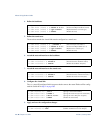
3. Enable OSPF.
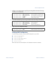
4. Define the backbone.
This version of Alteon OS requires that a backbone index be configured on the non-backbone
end of the virtual link as follows:
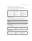
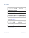
5. Define the transit area.
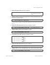
>> # /cfg/l3/if 1 (Select menu for IP interface 1)
>> IP Interface 1 # addr 10.10.12.2 (Set IP address on transit area net-
work)
>
> IP Interface 1 # mask 255.255.255.0 (Set IP mask on transit area network)
>> IP Interface 1 # enable (Enable IP interface 1)
>> IP Interface 1 # ../if 2 (Select menu for IP interface 2)
>> IP Interface 2 # addr 10.10.24.1 (Set IP address on stub area network)
>
> IP Interface 2 # mask 255.255.255.0 (Set IP mask on stub area network)
>> IP Interface 2 # enable (Enable IP interface 2)
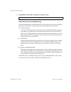
>> IP Interface 2 # /cfg/l3/rtrid 10.10.14.1
(Set static router ID on switch 2)
>> IP# /cfg/l3/ospf/on (Enable OSPF on switch 2)
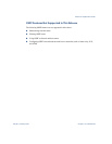
>> Open Shortest Path First # aindex 0 (Select the menu for area index 0)
>> OSPF Area (index) 0 # areaid 0.0.0.0 (Set the area ID for OSPF area 0)
>> OSPF Area (index) 0 # enable (Enable the area)
>> OSPF Area (index) 0 # ../aindex 1 (Select menu for area index 1)
>> OSPF Area (index) 1 # areaid 0.0.0.1 (Set the area ID for OSPF area 1)
>> OSPF Area (index) 1 # type transit (Define area as transit type)
>> OSPF Area (index) 1 # enable (Enable the area)